Plasma arc torch and method for improved life of plasma arc torch consumable parts

a technology of plasma arc torch and consumable parts, which is applied in plasma technique, manufacturing tools, welding apparatus, etc., can solve the problems of gas heating and ionization, and achieve the effect of increasing the useful life of consumable parts and enhancing the convective cooling of consumable parts

Inactive Publication Date: 2006-10-26
THERMAL DYNAMICS
View PDF9 Cites 29 Cited by
  • Summary
  • Abstract
  • Description
  • Claims
  • Application Information

AI Technical Summary

Benefits of technology

[0007] Among the several objects and features of the present invention is the provision of a plasma are torch which enhances convective cooling of the consumable parts of the torch; the provision of such a torch in which the useful life of the consumable parts is increased; and the provision of such a torch in which the electrode is capable of a threadless quick connect / disconnect connection with the cathode of the torch.
[0008] Among additional objects and features of the present invention is the provision of a method which increases the useful life of the consumable parts of a plasma arc torch; and the provision of such a method which enhances convective cooling of the consumable parts of the torch.

Problems solved by technology

When a sufficiently high voltage is applied to the electrode, an arc is caused to jump the gap between the electrode and the torch tip, thereby heating the gas and causing it to ionize.

Method used


Image

  • Plasma arc torch and method for improved life of plasma arc torch consumable parts
  • Plasma arc torch and method for improved life of plasma arc torch consumable parts
  • Plasma arc torch and method for improved life of plasma arc torch consumable parts

Examples


first embodiment

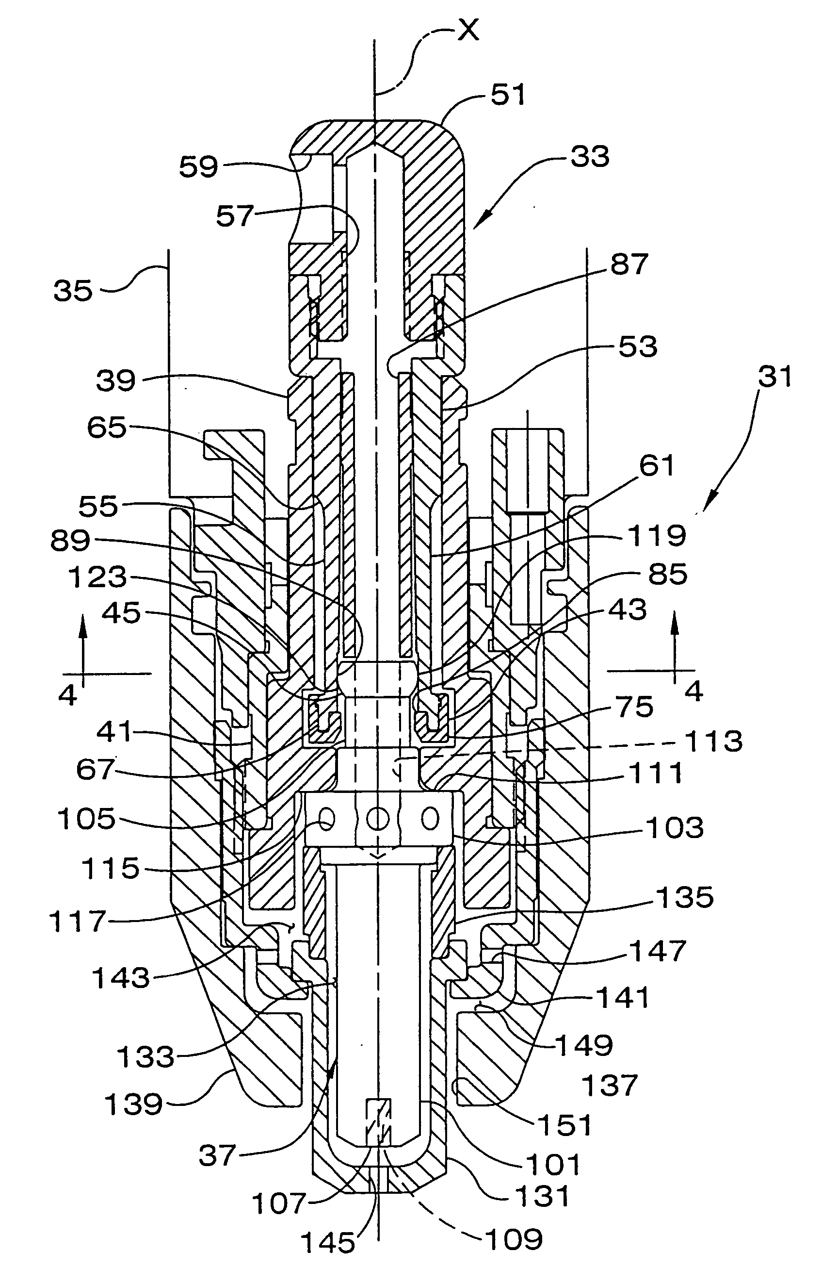
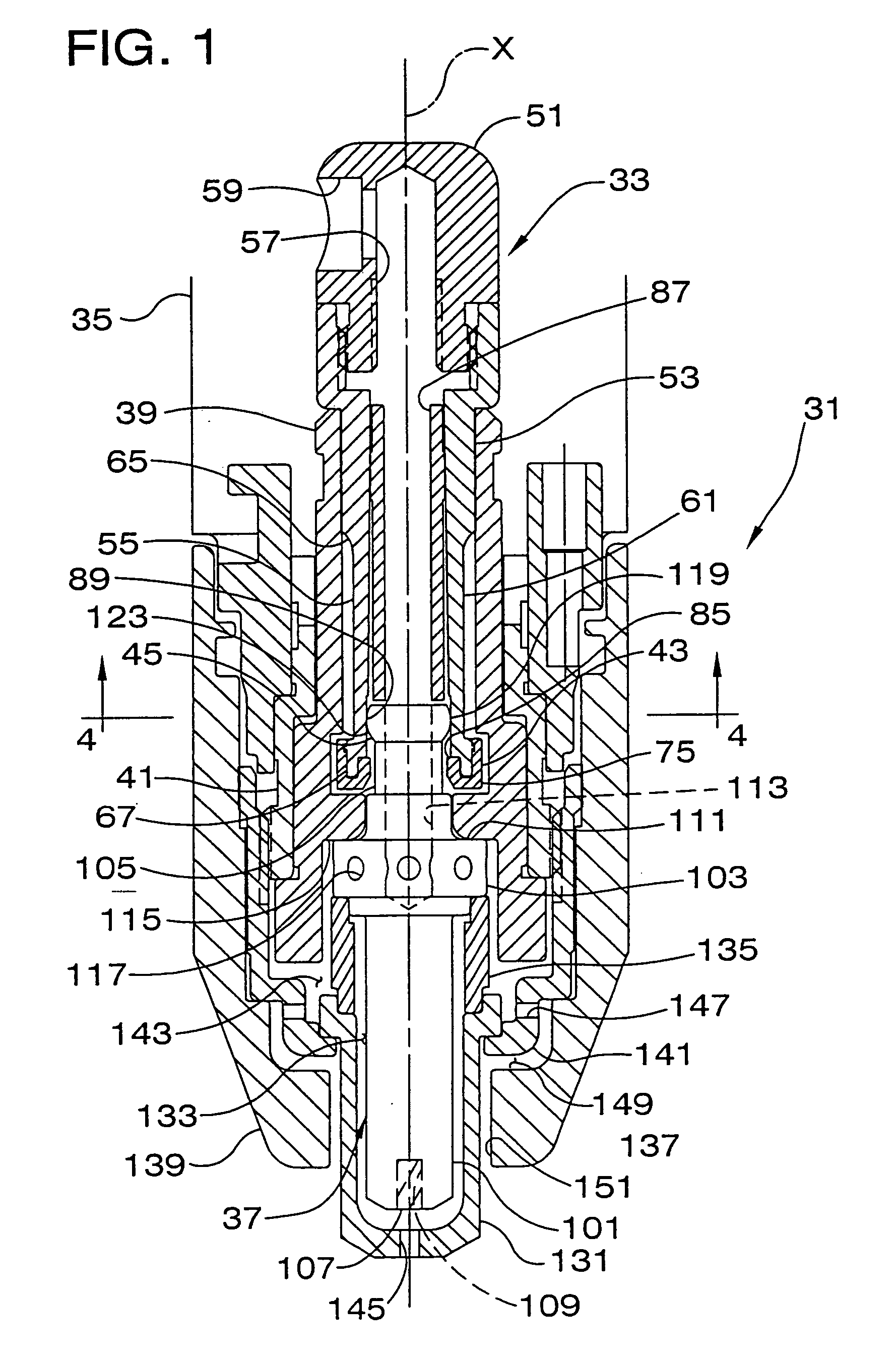
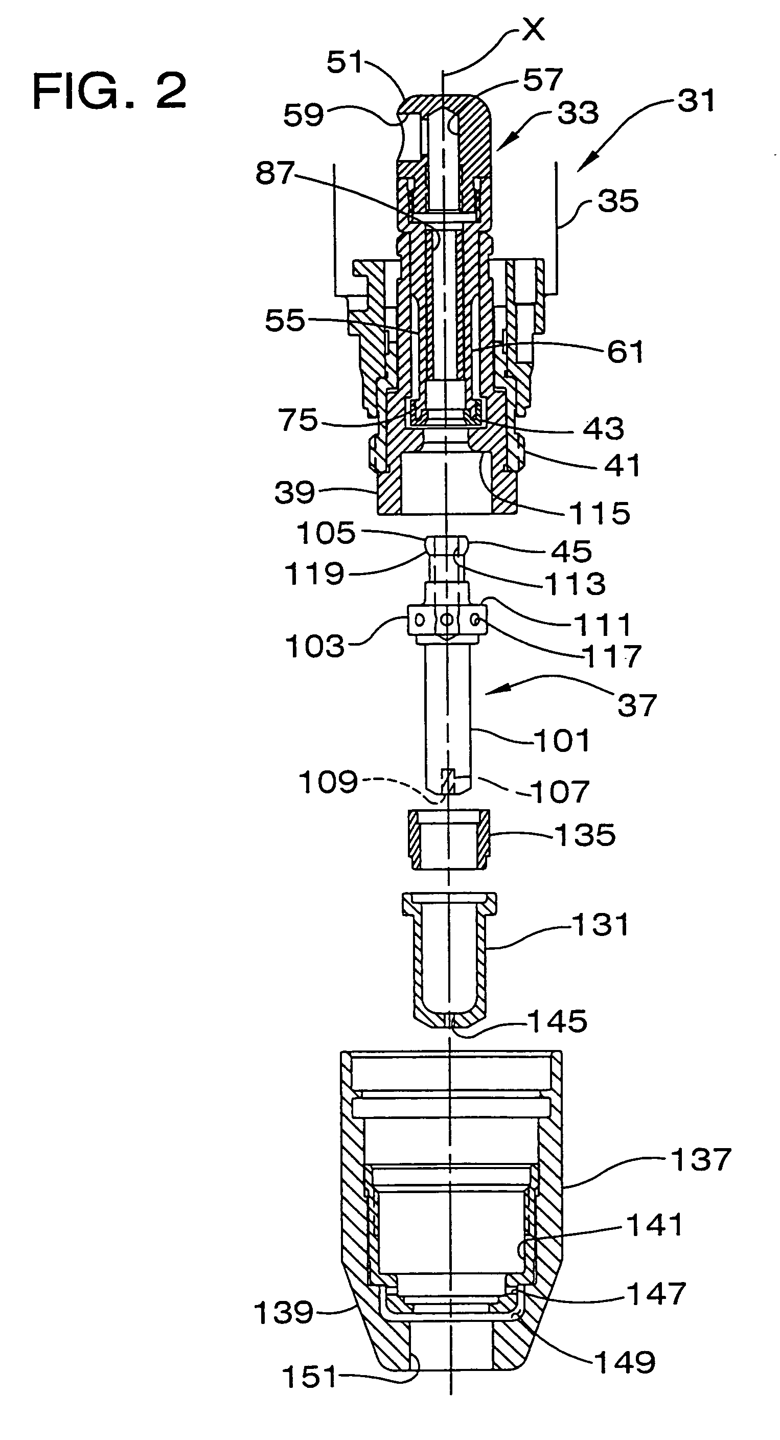
[0057] As illustrated in FIGS. 1-5 and described above, the plasma torch of this first embodiment incorporates an interconnecting cathode 33 and electrode 37 in which the electrode is inserted into the cathode. Alternatively, the electrode 37 may instead be sized and configured for surrounding the cathode 33, with the electrode detent 45 extending radially inward from the electrode connecting end 105 and the cathode detent 43 projecting radially outward from the cathode connecting end 55 such that the cathode prongs 61 are deflected inward upon relative telescoping movement of the cathode and electrode.

[0058]FIGS. 6-9 illustrate a second embodiment of a plasma torch of the present invention in which an electrode 237 (as opposed to the cathode 33 of the first embodiment) has a connecting end 305 comprising resilient longitudinally extending prongs 361. As with the first embodiment described above, the torch of this second embodiment includes a cathode, generally indicated at 233, the...

second embodiment

[0059] In this second embodiment, the central insulator 239 and electrode 237 are formed with radially opposed detents, generally designated 243 and 245, respectively. These detents 243, 245 are interengageable with one another when the electrode 237 is inserted in the torch head 231 to inhibit axial movement of the electrode relative to the central insulator outward from the torch.

[0060] As shown in FIG. 6, the cathode 233 is substantially similar to the cathode 33 of the first embodiment, comprising a head 251, a body 253 and a lower connecting end 255. A central bore 257 extends longitudinally substantially the entire length of the cathode 233 to direct a working gas through the cathode. The connecting end 255 of the cathode 233 is generally of rigid construction and is formed of brass, free of the electrically insulating sleeve 87 and end caps 75 described above in connection with the first embodiment. The diameter of the inner surface of the cathode connecting end 255 is jogged...


PUM

PropertyMeasurementUnit
inner diameter D1aaaaaaaaaa
inner diameter D2aaaaaaaaaa
outer diameteraaaaaaaaaa

Abstract

A plasma arc torch and method for improving the life of the consumable parts of the plasma are torch, including the electrode, the tip and the shield cap. The method includes turbulating gas as it flows over the exposed surfaces of the electrode, tip and shield cap to increase turbulence in the hydrodynamic boundary layer of the gas flow, thereby enhancing convective heat transfer. The result of enhanced cooling is improved consumable parts life. For example, to increase the turbulence of the gas flow over the outer surface of the electrode, the plasma arc torch electrode has a roughened, or textured outer surface formed with dimples, axially extending grooves or spiraling grooves formed in the outer surface of the electrode. The inner and outer surfaces of the tip and the inner surface of the shield cap are similarly textured.

Description

CROSS-REFERENCE TO RELATED APPLICATION [0001] The present application is a continuation of U.S. application Ser. No. 09 / 821,868 titled “Plasma Arc Torch and Method for Improved Life of Plasma Arc Torch Consumable Parts,” filed Mar. 30, 2001, the contents of which are incorporated herein by reference in their entirety and continued preservation of which is requested.BACKGROUND OF THE INVENTION [0002] The present invention relates generally to plasma arc torches and, in particular, to consumable parts utilized in plasma arc torches and methods for improving the useful life of such consumable parts. [0003] Plasma arc torches, also known as electric arc torches, are commonly used for cutting and welding metal workpieces by directing a plasma consisting of ionized gas particles toward the workpiece. In a typical plasma torch, a gas to be ionized is supplied to a lower end of the torch and flows past an electrode before exiting through an orifice in the torch tip. The electrode, which is ...

Claims


Application Information

Patent Timeline
Patent Type & Authority Applications(United States)
IPC IPC(8): B23K9/00B23K9/02H05H1/34
CPCH05H2001/3478H05H1/34H05H1/3478
Inventor HORNER-RICHARDSON, KEVIN D.SMALL, DAVID A.ROBERTS, JESSE A.
Owner THERMAL DYNAMICS
Why Eureka
Try Eureka