
Corner protector

Inactive Publication Date: 2006-11-02
CAOUTCHOUC & PLASTIQUES FALPACO
View PDF41 Cites 63 Cited by
  • Summary
  • Abstract
  • Description
  • Claims
  • Application Information

AI Technical Summary

Benefits of technology

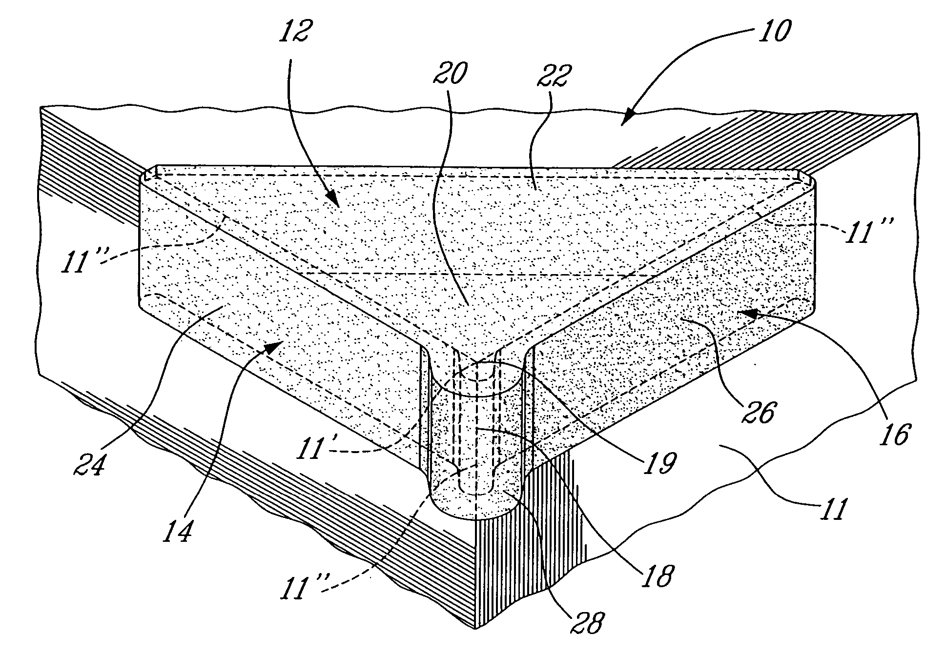
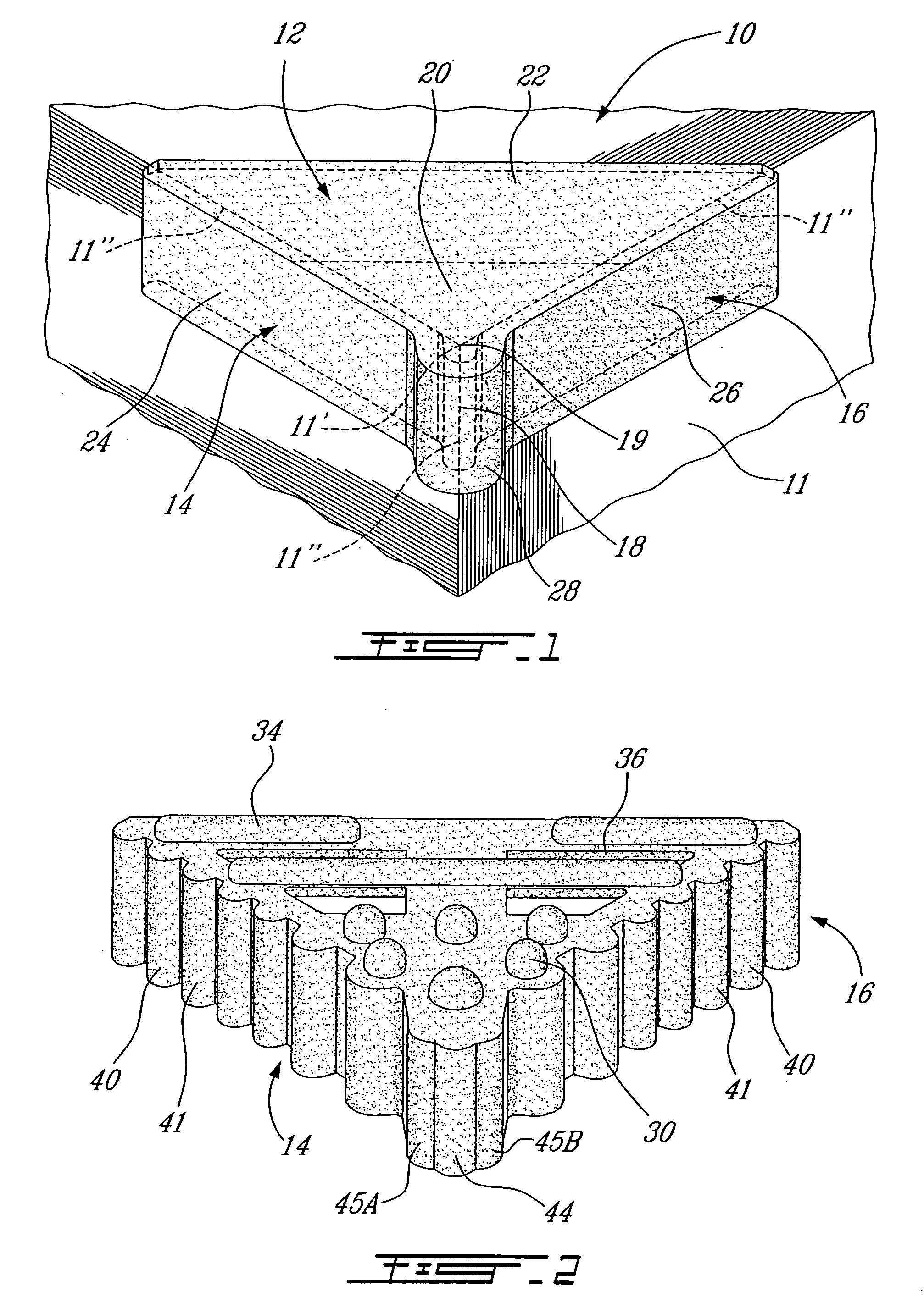
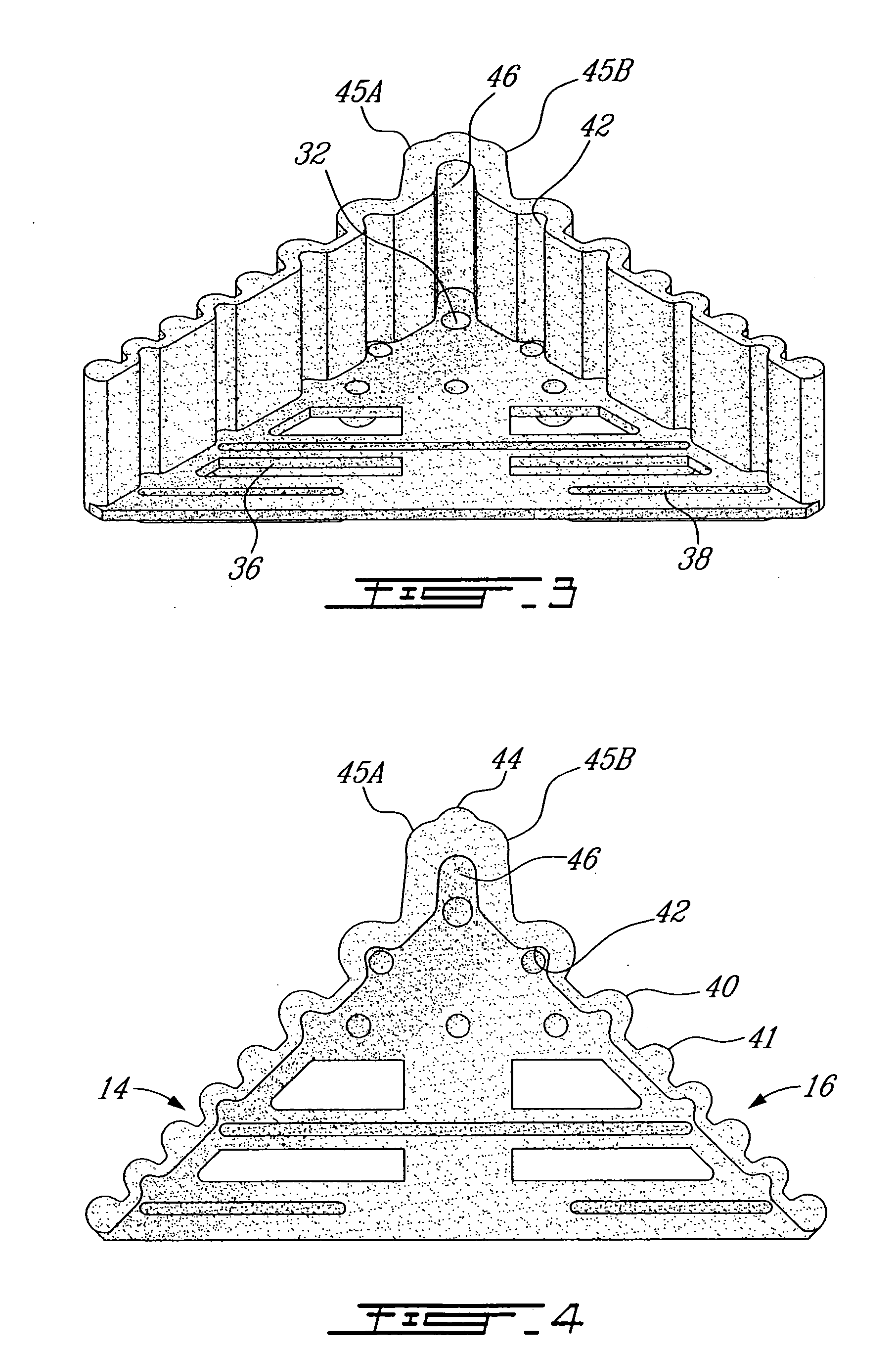
[0010] Therefore, in accordance with the present invention, there is provided a corner protector for protecting a corner of merchandise, comprising a first portion contacting a first surface of the merchandise; a second portion interconnected with the first portion, and contacting a second surface of the merchandise; a third portion interconnected with the first portion and the second portion, and contacting a third surface of the merchandise, in such a way that a corner of the merchandise at the intersection of the first, second and third surfaces is covered by the corner protector; and a first zone of protection located at the intersection of the second portion and the third portion, the first zone of protection having a corner protrusion defining a hollow recess so as to form an empty space along an edge of the corner of merchandise, whereby an impact on the corner protrusion will have its energy distributed by the corner protrusion to the second and third portions so as to generally prevent contact between said edge of the corner of merchandise and an inner surface of the corner protrusion.

Problems solved by technology

The storing, shipping and handling of manufactured goods such as furniture and appliances can damage the edges, corners and surfaces of the goods if they are not otherwise protected.
Collisions can cause edges and corners to be scratched or crushed, and surfaces to be damaged, and this often results in a devaluation of the goods.
These prior-art devices are not durable and suffer from minimal reusability due to the material from which they are made.
This has the disadvantage of potentially damaging the surface of the structure being protected.
The adhesive also makes the device cumbersome in an industrial setting and limits its reusability.
The described device has a bulbous portion rendering it impractical for packaging, stacking and shipping.

Method used


Image

  • Corner protector
  • Corner protector
  • Corner protector

Examples


Embodiment Construction

[0017] Referring now to the drawings, and more particularly to FIG. 1, a corner protector in accordance with the preferred embodiment of the present invention is generally shown at 10 protecting merchandise 11.

[0018] The corner protector 10 comprises three main portions, which are coplanar to the three surfaces defining the corner of merchandise 11 that is to be protected. The corner protector 10 is designed to fit over and protect a corner 11′ and edges 11″ of merchandise 11. For example, the corner protector 10 can protect the corners of furniture, appliances, machinery or merchandise having corners that one wishes to protect from scratching, scraping or crushing during storing, shipping and handling.

[0019] A first portion 12 of the corner protector 10 is generally triangular. A second portion 14 extends downward from a first edge of the first portion 12 and is generally perpendicular to the first portion 12. A third portion 16 extends downward from a second edge of the first po...


PUM


Abstract

A corner protector for protecting a corner of merchandise, comprising a first portion contacting a first surface of the merchandise. A second portion is interconnected with the first portion, and contacts a second surface of the merchandise. A third portion is interconnected with the first portion and the second portion, and contacts a third surface of the merchandise, in such a way that a corner of the merchandise at the intersection of the first, second and third surfaces is covered by the corner protector. A first zone of protection is located at the intersection of the second portion and the third portion, the first zone of protection having a corner protrusion defining a hollow recess so as to form an empty space along an edge of the corner of merchandise, whereby an impact on the corner protrusion will have its energy distributed by the corner protrusion to the second and third portions so as to generally prevent contact between said edge of the corner of merchandise and an inner surface of the corner protrusion.

Description

BACKGROUND OF THE INVENTION [0001] 1. Field of the Invention [0002] The present invention relates to a corner protector for protecting merchandise, such as furniture, appliances and raw materials, from being damaged by impact during shipping or other transportation. [0003] 2. Background Art [0004] The storing, shipping and handling of manufactured goods such as furniture and appliances can damage the edges, corners and surfaces of the goods if they are not otherwise protected. Collisions can cause edges and corners to be scratched or crushed, and surfaces to be damaged, and this often results in a devaluation of the goods. Consequently, it is desirable to provide a low-cost device that can protect these manufactured goods during shipping and handling. [0005] Prior-art devices have been developed to help protect goods during shipping and handling. For example, U.S. Pat. No. 5,175,041, issued on Dec. 29, 1992 to Webb et al., describes a corner protector, which is formed entirely of pa...

Claims


Application Information

Patent Timeline
IPC IPC(8): B65D81/02
CPCB65D81/053B65D81/056B65D2581/055
Inventor ROBICHAUD, CLAUDETANGUAY, JEAN
Owner CAOUTCHOUC & PLASTIQUES FALPACO
Learn More