
Bar clip with flared legs

a technology of flared legs and clips, which is applied in the direction of roofs, building components, roof coverings, etc., can solve the problems of more labor-intensive methods, increased costs, and labor-intensive methods of attaching bars, and the use of clips with transversely oriented reinforcement bars

Inactive Publication Date: 2006-11-09
KODI KLIP LLC
View PDF90 Cites 26 Cited by
  • Summary
  • Abstract
  • Description
  • Claims
  • Application Information

AI Technical Summary

Benefits of technology

[0012] Finally, it is an object of the present invention to provide a means of guiding a reinforcement bar into a clasp during installation of the clip.
[0010] Accordingly it is an object of the present invention to provide a reinforcement bar clip that can be used to attach adjacent reinforcing bars arranged in a parallel orientation.
[0012] Finally, it is an object of the present invention to provide a means of guiding a reinforcement bar into a clasp during installation of the clip.

Problems solved by technology

However, both means are labor intensive and, thus, more expensive when compared to the use of more recently developed reinforcing bar clips.
These clips can only be used with transversely oriented reinforcement bars.
However, frameworks of reinforcement bars frequently require attachment of bars in parallel orientations as well as transverse orientations.
All other attachment orientations require the user to employ more labor intensive methods of attaching the bars, such as wire wrap.

Method used


Image

  • Bar clip with flared legs
  • Bar clip with flared legs
  • Bar clip with flared legs

Examples


Embodiment Construction

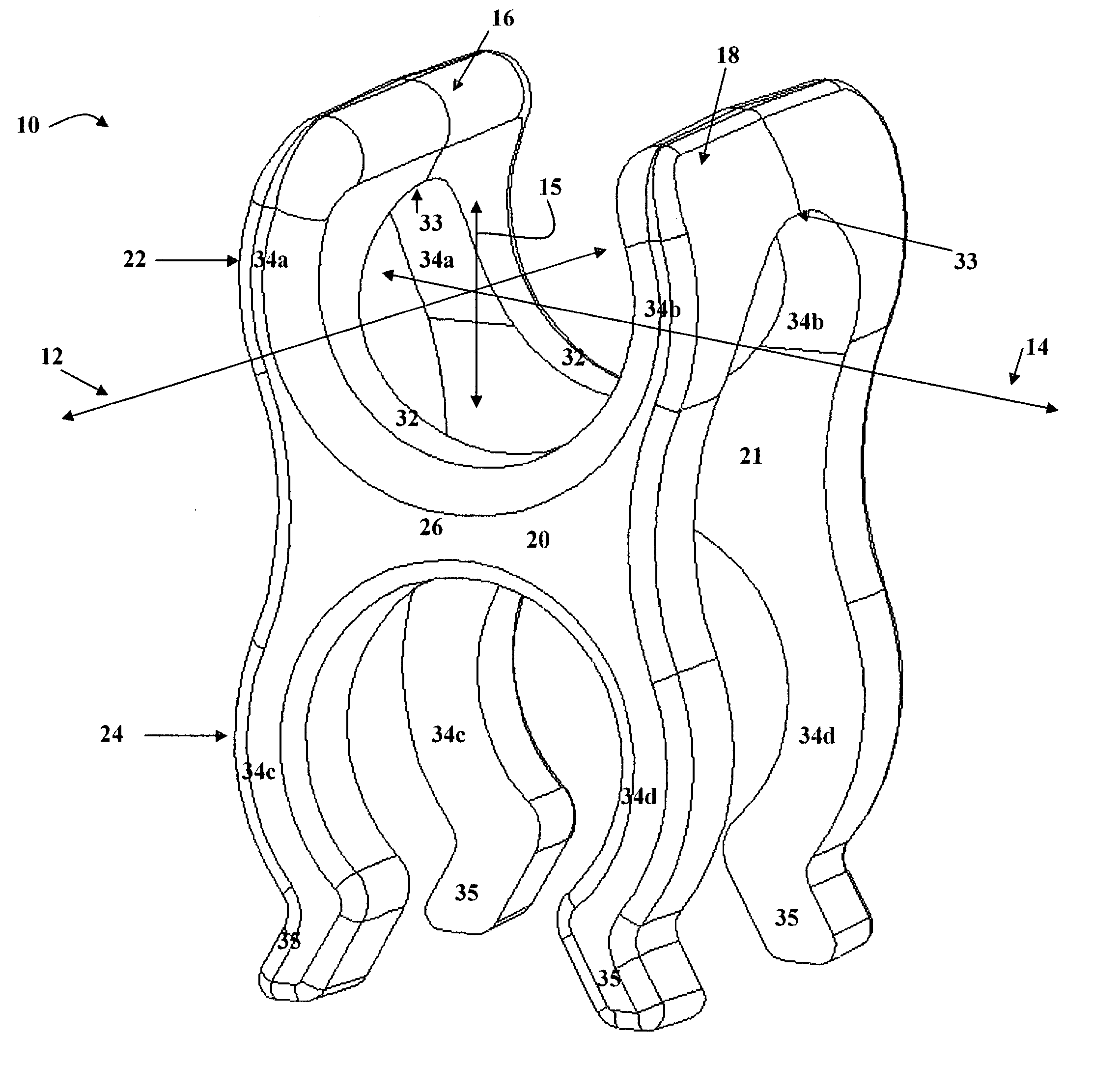
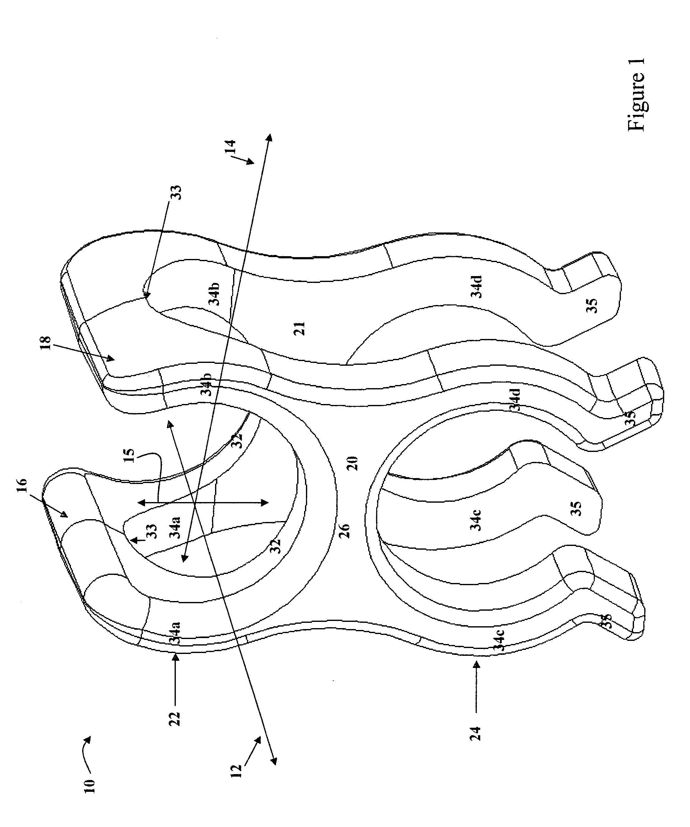
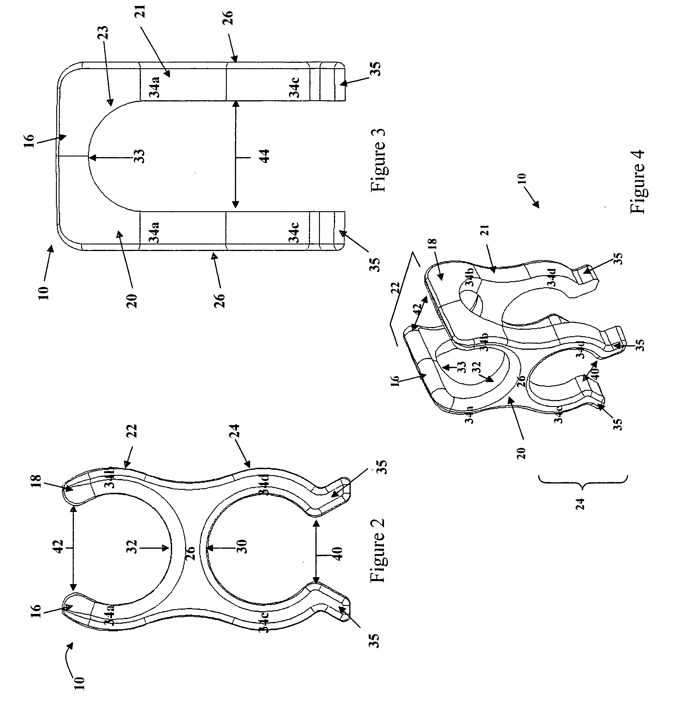
[0019] One preferred embodiment of the reinforcement bar clip 10 of the present invention is shown in FIG. 1, wherein orientation of the clip 10 is shown with reference to the vertical direction arrow 15, the longitudinal direction arrow 12 and the transverse direction arrow 14. The embodiment shown in FIG. 1 is a molded plastic clip 10 made of a resilient plastic material having a color selected to indicate the appropriate gauge of reinforcement bars upon which it may be installed. The clip 10 comprises a plurality of clasp assemblies. The embodiment shown in FIG. 1 comprises a pair of opposing first and second clasp assemblies 20, 21. Each first and second clasp assembly 20, 21 is attached to parallel first and second longitudinal supports 16, 18 and extends downward from the longitudinal supports 16, 18. The opposing first and second clasp assemblies 20, 21, together with the first and second longitudinal supports 16, 18, form a U-shaped profile, as is shown in FIG. 3.

[0020] Ref...


PUM

PropertyMeasurementUnit
coloraaaaaaaaaa
areaaaaaaaaaaa
pressureaaaaaaaaaa

Abstract

A color coded molded plastic clip comprising a pair of opposing clasp assemblies provides a means of holding a pair of reinforcement bars in a parallel orientation. Each clasp assembly comprises an upper clasp and a lower clasp. Each upper clasp includes a pair opposing, convexly curved fingers extending upward from a transverse support toward and attached to a pair of parallel longitudinal supports. Each clasp assembly further includes a second pair of opposing, convexly curved fingers extending downward from either end of the transverse support so as to form a lower clasp. Flared guides are attached to the lower ends of the opposing fingers of each lower clasp. During installation of the lower clasp of the clip upon a reinforcement bar, the pair of flared guides engages the bar and guides it to the lower clasp gap for insertion into the lower clasp.

Description

BACKGROUND OF THE INVENTION [0001] The present invention relates generally to an apparatus and method of attaching and aligning reinforcing bars in a framework for supporting a concrete matrix. More particularly, this invention pertains to clips for joining reinforcing bars in a framework. Even more particularly, this invention pertains to a clip with flared legs for joining pairs of reinforcing bars in a parallel orientation. [0002] It has been long known in the art of reinforced concrete structures to provide fastening means for aligning and attaching reinforcing bars in a framework prior to encasing such bars in a concrete matrix. One well known fastening means used in forming a framework of reinforcing bars is to wrap adjacent bars with wire ties, or other similar binding materials. Another well known fastening means is to attach such reinforcing bars by welding instead of wrapping. Both of these fastening means provide for attaching bars arranged in either transverse or paralle...

Claims


Application Information

Patent Timeline
Patent Type & Authority Applications(United States)
IPC IPC(8): E04D1/00E04B1/38
CPCE04C5/163E04C5/20E04C5/167Y10S52/01
Inventor KODI, JON R.
Owner KODI KLIP LLC
Learn More