Wing holder

a technology of finger manipulation and wing, which is applied in the direction of pliers, thin material handling, tableware, etc., can solve the problems of undesired stuck residues of coatings on consumers' hands, no device combine a specialized jaw structure with the ability to clench and manipulate foods

Inactive Publication Date: 2006-11-09
CAROLINA RAYMOND H
View PDF26 Cites 17 Cited by
  • Summary
  • Abstract
  • Description
  • Claims
  • Application Information

AI Technical Summary

Benefits of technology

[0017] A notch is defined by the terminal free ends of the first row of teeth. The second rows of teeth on each arm have a height that extends from the straight axis of that arm that is less than or equal to the height of the first row of teeth from the straight axis of that arm.

Problems solved by technology

The popularity of appetizers, hors d'oeuvres, and other courses that include foods such as chicken pieces, chicken wings and ribs has also created less than favorable circumstances for consumers.
Eating these foods commonly leaves the remnants of these coatings undesirably stuck to the hands of the consumer.
Similar problems occur when pieces of food are dipped into a sauce, dip or melted butter, for example, and the dip drips on to the hand of the consumer.
While a number of tong type devices exist, none of the devices combine a specialized jaw structure with the ability to clench and manipulate foods for the ease of consumption by the consumer.

Method used


Image

  • Wing holder
  • Wing holder
  • Wing holder

Examples


second embodiment

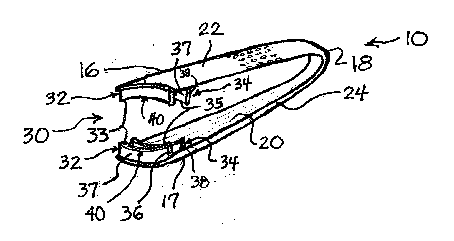
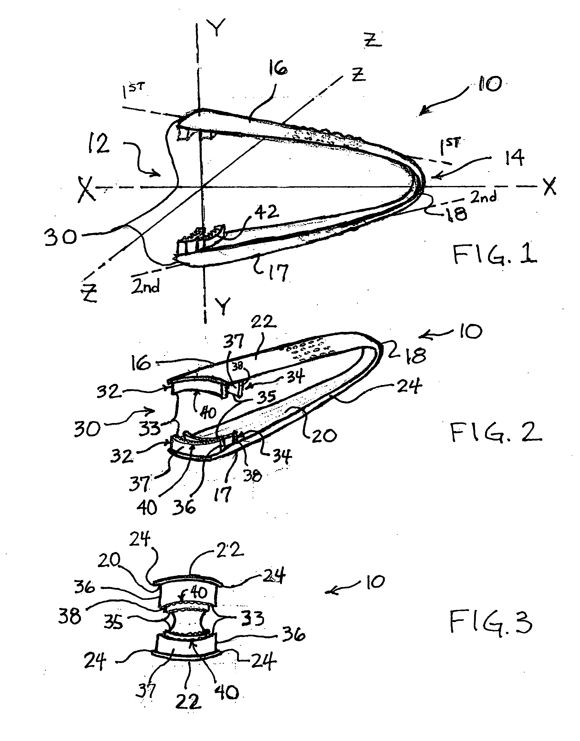
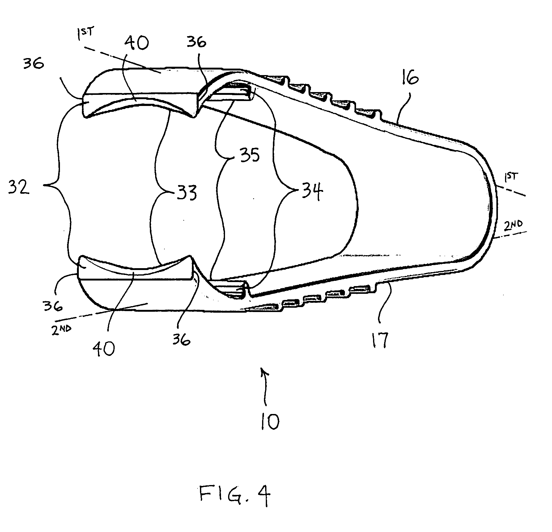
[0045] Referring now to FIGS. 4 and 5, wing holder 10 includes arms 16 and 17 being connected by joint 18 as described previously. The distal end portions of arms 16 and 17 have an arcuate shape that extends at least partially in an inward direction from the first and second axes, respectively. Arms 16 and 17 have an approximately rectangular cross-sectional shape in a plane Y-Z, defined by axes Y and Z (see FIG. 1) in this preferred embodiment. Set of teeth 32 extend inwardly from arms 16 and 17 at an angle that is approximately perpendicular to the first and second axes. Alternatively, the distal end portion of arms 16 and 17 can be truncated to define set of teeth 32. Set of teeth 34 is positioned proximal to set of teeth 32 in each jaw 30 as described previously.

[0046] As shown in FIGS. 4-6, each row of teeth 33 preferably has a single tooth that with a tapered edge that extends between longitudinal edges 36. The edges of rows of teeth 33 define notch 40 as described previously ...

third embodiment

[0056] Referring to the third embodiment as shown in FIGS. 9 -14, when forces-A are applied to the proximal end portion of arms 16 and 17, arms 16 and 17 flex about joint 18 from the first closed position to the second open position. In the second position, the selected piece of food is positioned between the opened jaws 30 and the piece of food is retained in jaws 30 by removing at least one of forces-A applied to arm 16 and arm 17. Upon the removal of forces-A, the resilience of joint 18 moves jaws 30 to the closed position securely seizing the selected piece of food. The selected piece of food is then released by the application of force-A on the proximal end portions of arms 16 and / or 17 to move jaws 30 to the second open position.


PUM


Abstract

A wing holder is described that includes a pair of arms that are connected by a joint. The joint provides a flexible hinge for the movement of the arms between a first and second position for the seizing and engagement of appetizers, hors d'oeuvres, and other courses that include food pieces such as chicken wings and ribs. Jaws are positioned on the distal ends of the arms that include a distal first row of teeth and a second proximal row of teeth. The distal first row of teeth defines a notch for the retention of the food pieces during the eating process. The second row of teeth also engages and assists in the retention of the food pieces in the wing holder.

Description

[0001] This application claims the benefit of U.S. Provisional Application 60 / 671,246 filed on 14 Apr. 2005.FIELD OF THE INVENTION [0002] The present invention relates to devices that clench food pieces and more specifically to finger manipulated devices that assist in the eating of food. BACKGROUND OF THE INVENTION [0003] Tong devices are structured for the seizing and holding food. The typical tong structure includes a joint that connects a pair of arms that have opposed jaws. The jaws have a specialized structure for their intended function and can move between an open and a closed position. [0004] The specialized structure of the jaw of each kind of tong provides functional advantages that can also limit that same tong in other applications. For example, ice tongs have sharp pointed teeth in each jaw and a length that is adept for seizing and transferring a cube of ice from an ice bucket to a glass. In contrast, barbecues tongs have an extended arm length and jaws with teeth for...

Claims


Application Information

Patent Timeline
Patent Type & Authority Applications(United States)
IPC IPC(8): B25B9/00B25B7/00
CPCA47G21/10Y10S294/902B25B9/02
Inventor CAROLINA, RAYMOND H.
Owner CAROLINA RAYMOND H
Why Eureka
Try Eureka