Stud framing brace

a technology of framing brace and stud, which is applied in the direction of building construction, building material handling, construction, etc., can solve the problem of difficult use of methods for individuals working individually

Inactive Publication Date: 2006-11-23
RIDDLE MARLIN +1
View PDF15 Cites 23 Cited by
  • Summary
  • Abstract
  • Description
  • Claims
  • Application Information

AI Technical Summary

Problems solved by technology

Scrap pieces of wood have been cut to the proper length and held in place at both the top and bottom of the studs, but this method is difficult to use for a person working individually.

Method used


Image

  • Stud framing brace
  • Stud framing brace
  • Stud framing brace

Examples


Embodiment Construction

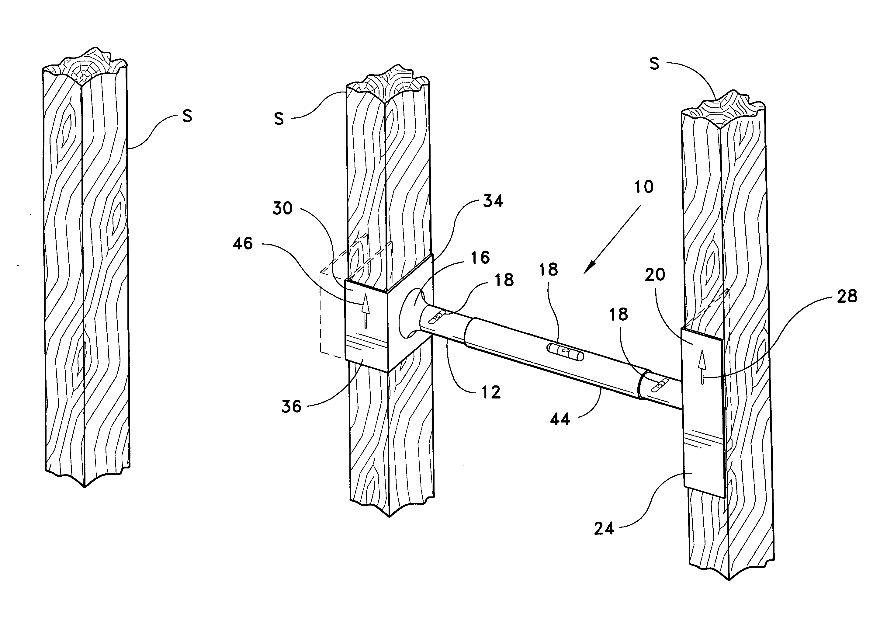
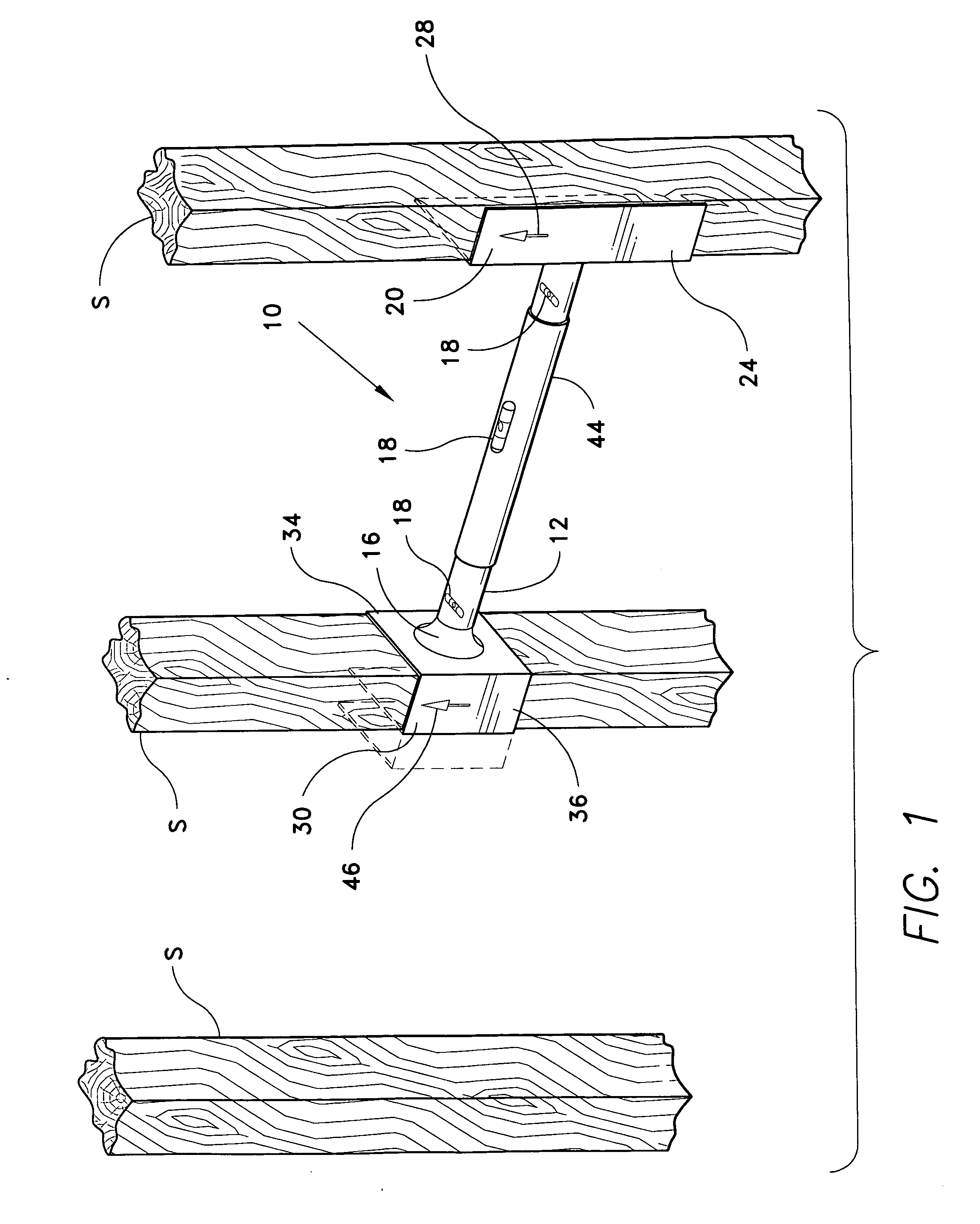
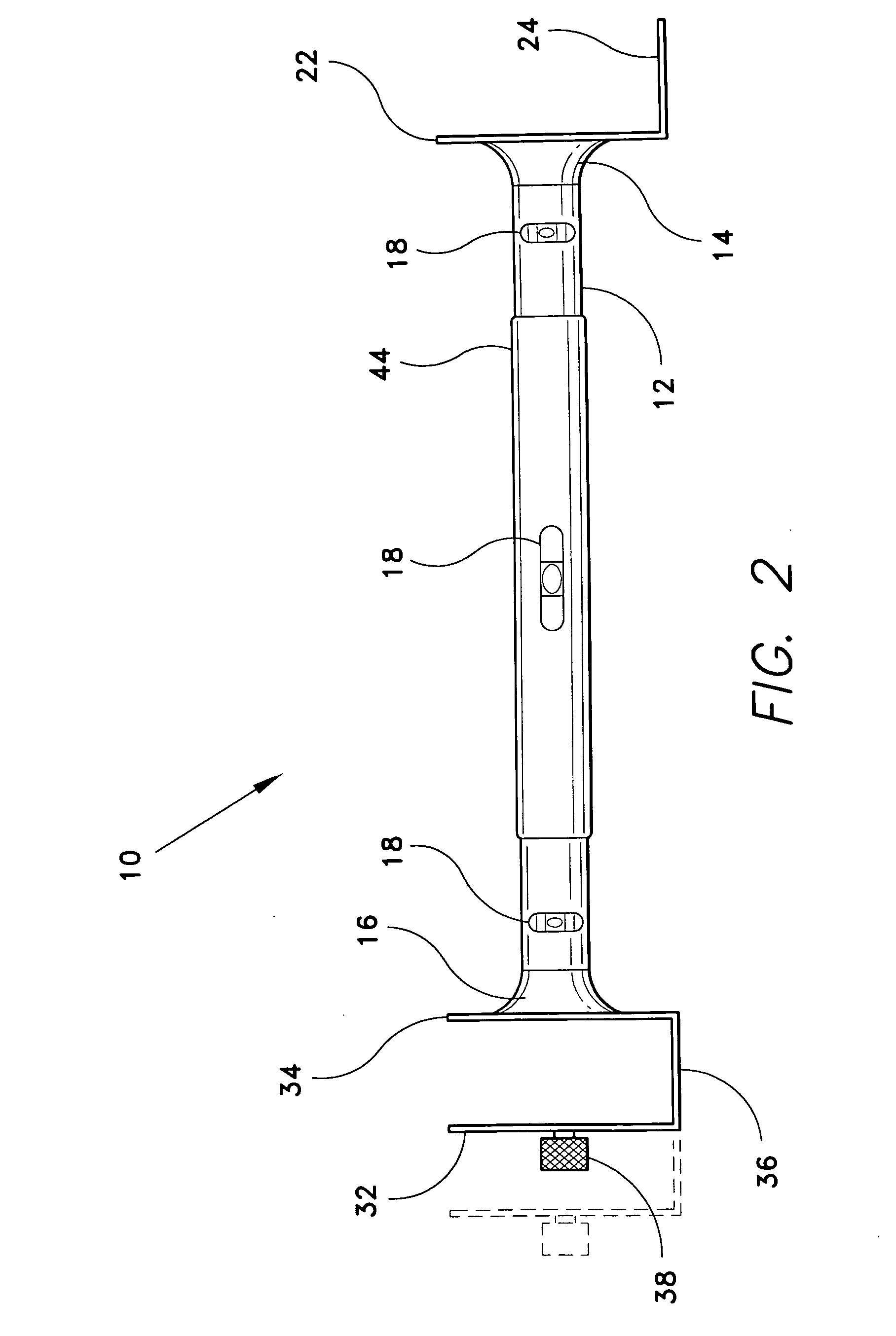
[0015] The present invention is a stud framing brace, designated generally as 10 in the figures. The stud framing brace 10 is a tool used in aligning and supporting wall studs S during the construction of a building. The brace 10 has a central arm 12 with a stud-receiving member 20 attached to a first end 14 of the arm 12 and a stud-clamping member 30 attached to a second end 16 of the arm 12. The stud-clamping member 30 may secure the brace 10 to an installed stud, while the stud-receiving member 20 allows a free stud to be rested against the brace 10.

[0016] When the free stud is moved into place in the frame, the side plate 22 and front plate 24 of the stud-receiving member 20 will contact the free stud, as shown in FIG. 1. The side plate 22 is arranged normal to the front plate 24, and is permanently secured to the front plate 24 along an entire edge. The front plate 24 may additionally include indicia 28 to indicate the location of the center of the stud S when positioned corre...


PUM


Abstract

The stud framing brace is a tool used in aligning and supporting wall studs during the construction of a building. The brace has a central arm with a stud-receiving member attached to a first end of the arm and a stud-clamping member attached to a second end of the arm. The stud-clamping member secures the brace to an installed stud, while the stud-receiving member may allow a free stud to rest against the brace. The arm may be extended to the proper standardized length to ensure the studs are properly spaced. Spirit levels disposed in the arm may be used to align the stud vertically.

Description

BACKGROUND OF THE INVENTION [0001] 1. Field of the Invention [0002] The present invention relates to wood framing tools. More specifically, the invention relates to hand-held jigs used to position, align and support wood studs or rafters during construction or repair of a wall, floor or roof. [0003] 2. Description of the Related Art [0004] In many finished buildings, two-by-four lumber is used for framing the walls, floors and roofs. Each section of framing is formed by assembling the lumber pieces into rectangular sections and securing a series of lumber pieces called studs into the sections. The frame is then secured to the foundation or another assembled section of framing. The studs are typically positioned in a regular, parallel relation spaced approximately sixteen inches on center. Most utilities and fixtures in the building are designed to fit into and connect to these parallel, regularly spaced studs. [0005] Various devices and methods have been used to make certain that th...

Claims


Application Information

Patent Timeline
Patent Type & Authority Applications(United States)
IPC IPC(8): E04G21/26
CPCE04G21/1891
Inventor RIDDLE, MARLINHUMPHREY, JACKY
Owner RIDDLE MARLIN
Why Eureka
Try Eureka