Valve with internal lifter

a valve and lifter technology, applied in the field of medical devices, can solve the problems of blood in the valve compromising the sterility of the valve and/or catheter, problems arise,

Active Publication Date: 2006-11-23
NP MEDICAL
View PDF99 Cites 23 Cited by
  • Summary
  • Abstract
  • Description
  • Claims
  • Application Information

AI Technical Summary

Problems solved by technology

Problems arise, however, when the syringe is withdrawn from the valve.
In addition to coagulating and impeding the

Method used


Image

  • Valve with internal lifter
  • Valve with internal lifter
  • Valve with internal lifter

Examples


Embodiment Construction

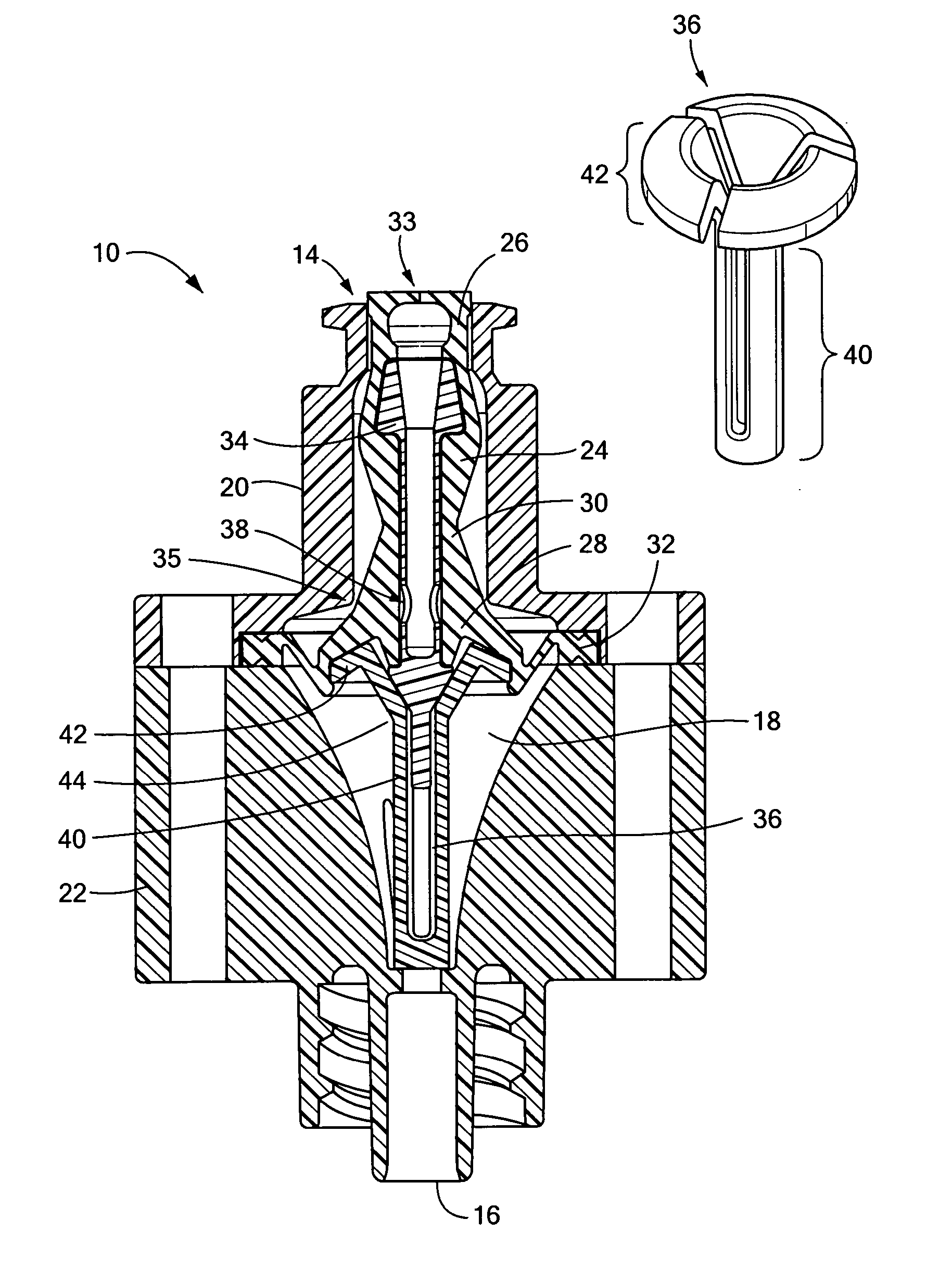
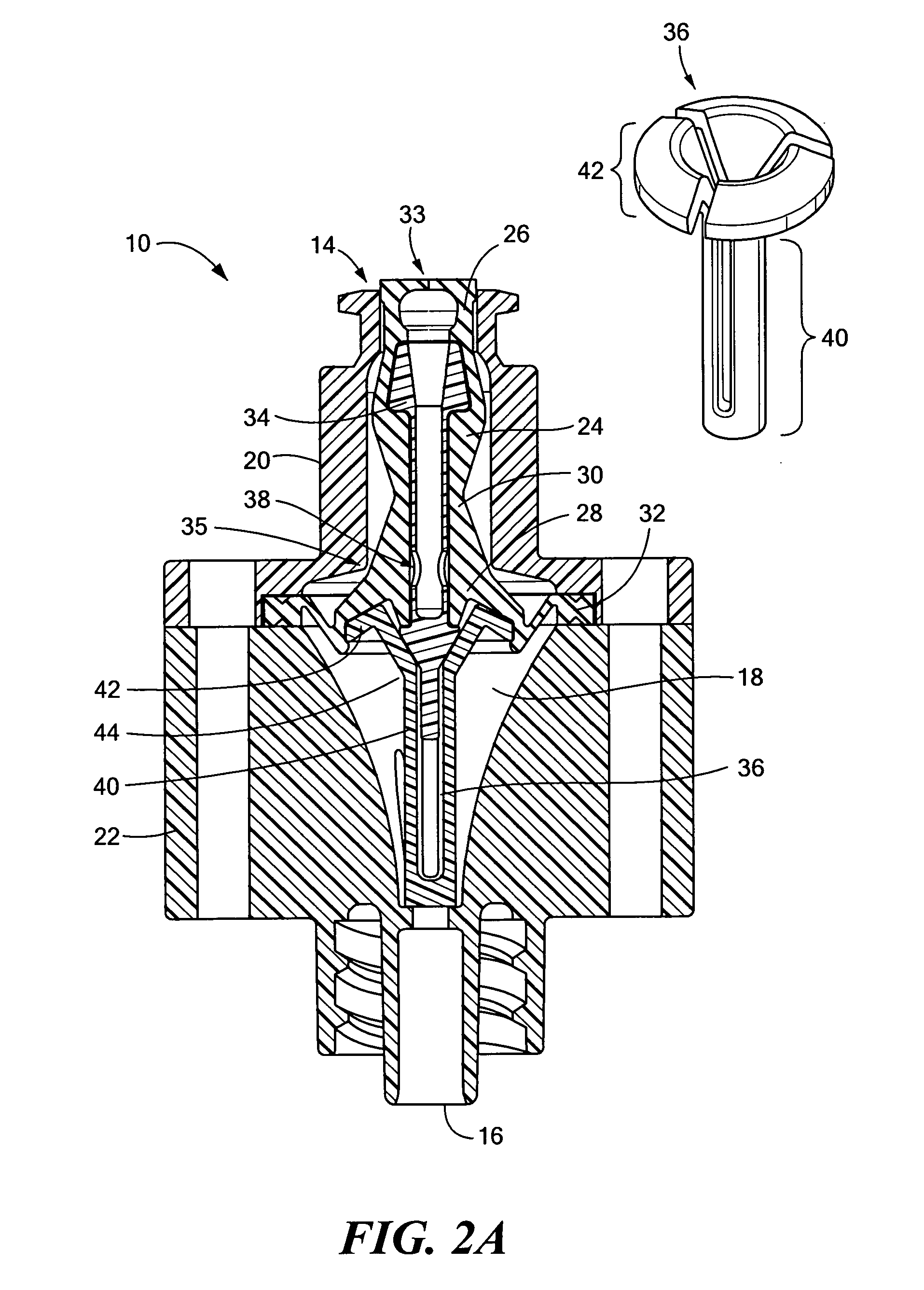
[0024] In illustrative embodiments of the invention, a valve produces a positive, distally directed pressure (i.e., toward its outlet) when a nozzle or syringe is withdrawn. Such pressure should prevent non-negligible amounts of fluid from s being drawn into the valve at such time. To these ends, the valve has an interior fluid chamber / flow channel sized and configured 1) to expand its volume as the valve transitions toward the open mode, and 2) to reduce its volume as the valve transitions toward the closed mode. Details of this and related embodiments also are discussed below.

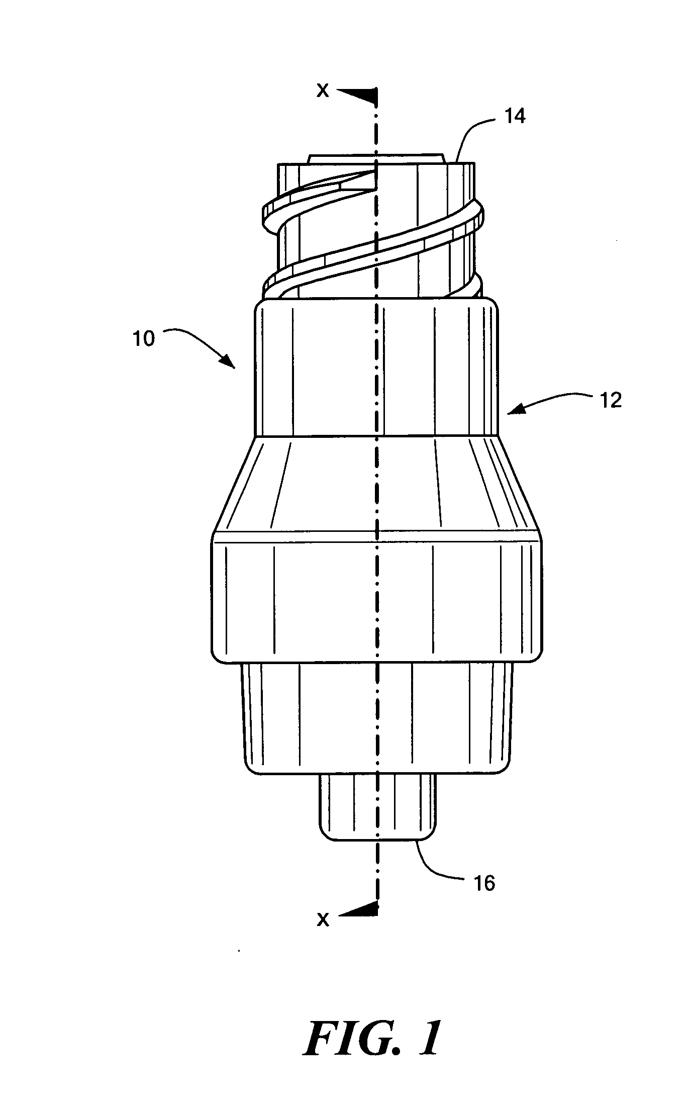
[0025]FIG. 1 schematically shows a medical valve 10 that is configured to reduce fluid drawback (a / k / a “back-flow,” noted above) when a syringe or other type of nozzle is withdrawn from it. The valve 10 has a valve body / housing 12 with proximal and distal ports 14 and 16 (also respectively referred to herein as “inlet 14” and “outlet 16”). The valve body has an internal chamber 18 containing a valve element ...


PUM


Abstract

A medical valve having a close mode and an open mode includes a housing having a proximal end, a distal end, and an interior. The valve also has a valve mechanism within the interior. In illustrative embodiments, the valve mechanism has a gland member and a lifter member. The lifter member moves the gland member toward the proximal end of the housing as the valve transitions from the closed mode to the open mode.

Description

RELATED APPLICATIONS [0001] This application is related to the following U.S. patents and U.S. patent applications, the disclosures of which are incorporated herein, in their entireties, by reference: [0002] U.S. Pat. No. 6,039,302 (Bromberg & Sunstein LLP attorney docket number 1600 / 114); [0003] U.S. Pat. No. 6,883,778 (Bromberg & Sunstein LLP attorney docket number 1600 / 121); [0004] U.S. Pat. No. 6,755,391 (Bromberg & Sunstein LLP attorney docket number 1600 / 145); [0005] U.S. application Ser. No. 10 / 224,299 (Bromberg & Sunstein LLP attorney docket number 1600 / 149); [0006] U.S. Pat. No. 6,869,426 (Bromberg & Sunstein LLP attorney docket number 1600 / 154); [0007] U.S. application Ser. No. 10 / 687,515 (Bromberg & Sunstein LLP attorney docket number 1600 / 162); and [0008] U.S. application Ser. No. 10 / 700,344 (Bromberg & Sunstein LLP attorney docket number 1600 / 163). PRIORITY [0009] This patent application claims priority from provisional U.S. patent application No. 60 / 644,068, filed Jan....

Claims


Application Information

Patent Timeline
IPC IPC(8): A61M5/00
CPCA61M39/02A61M2205/75A61M2039/263A61M39/26
Inventor COTE, ANDREW L. SR.NEWTON, BRIAN L.
Owner NP MEDICAL
Why Eureka
Try Eureka