
Molded insulating hinge for bipolar instruments

Inactive Publication Date: 2006-11-23
COVIDIEN AG
View PDF99 Cites 220 Cited by
  • Summary
  • Abstract
  • Description
  • Claims
  • Application Information

AI Technical Summary

Benefits of technology

The patent describes an electrosurgical instrument with a hinge assembly that is made from a variety of materials and can be securely held in place between two shafts. The hinge assembly is made from a composition of materials that insulates the end effectors from each other. The instrument also includes a retention tab and a stop member to limit the movement of the end effectors. The method of forming the hinge assembly involves mounting the shafts to a die block and introducing an overmold composition to encapsulate the hinge plates. A spacer can be used to maintain a gap distance between the end effectors during the molding and curing step. The technical effects of this patent include improved insulation between the end effectors, secure holding of the hinge assembly, and better control over the movement of the end effectors.

Problems solved by technology

These separately overmolded subassemblies are mechanically integrated and arranged in a series of manufacturing steps that often require tightly controlled and time consuming processes to achieve proper jaw alignment and reliable and consistent gap separation between electrodes.

Method used


Image

  • Molded insulating hinge for bipolar instruments
  • Molded insulating hinge for bipolar instruments
  • Molded insulating hinge for bipolar instruments

Examples


Embodiment Construction

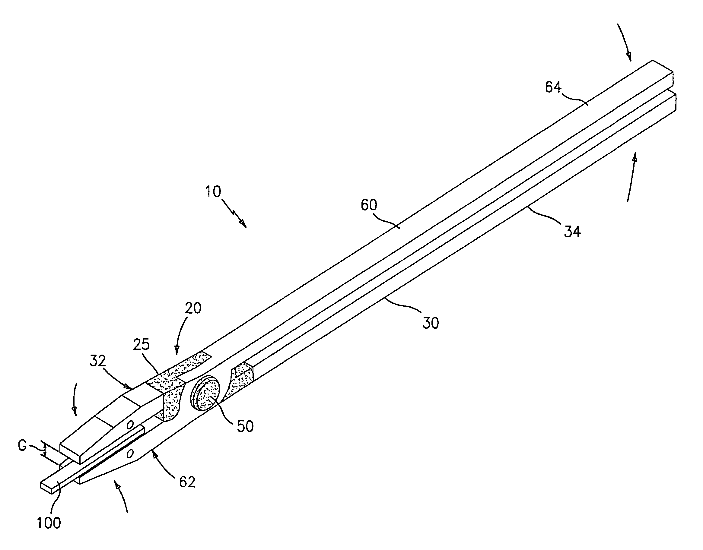
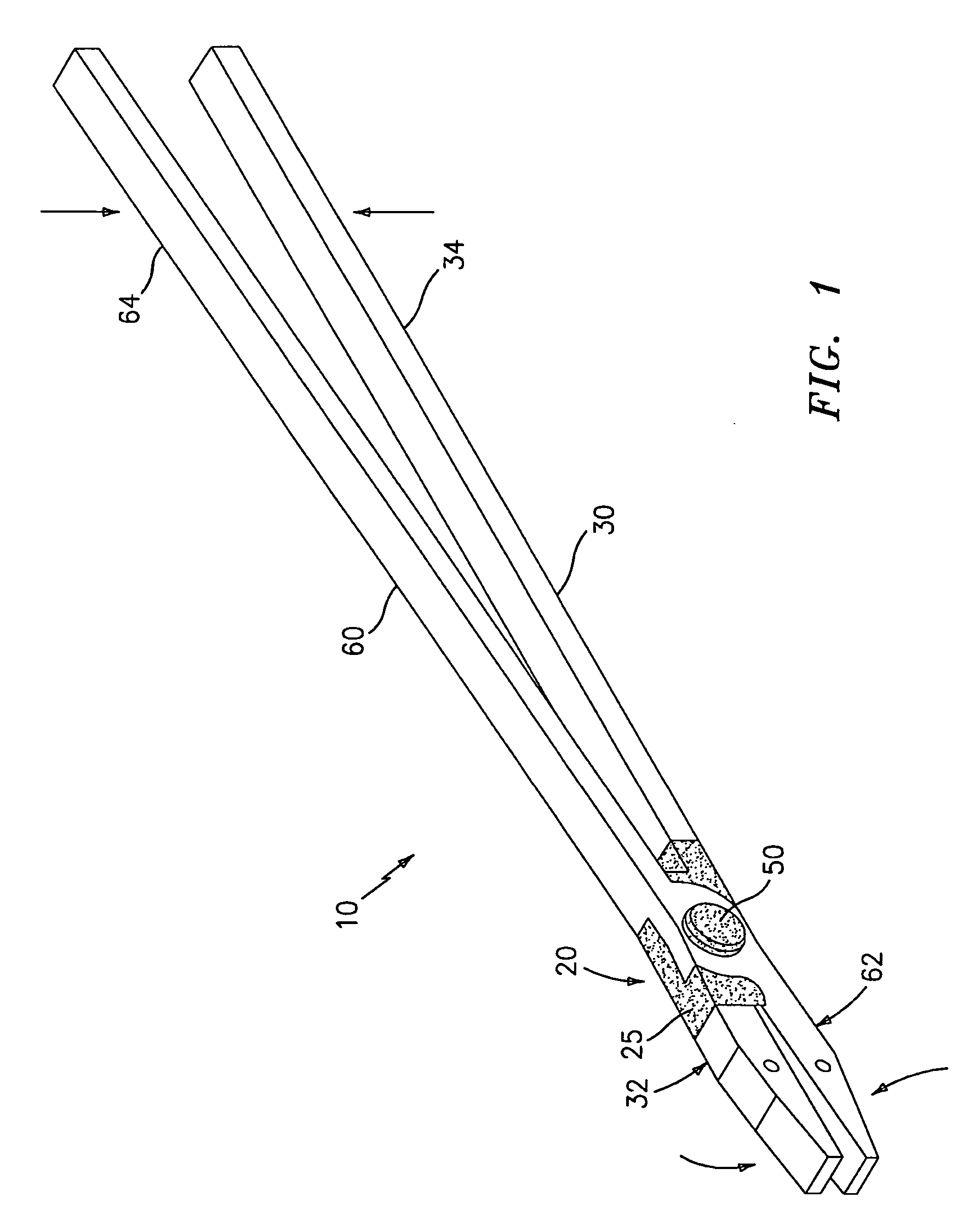
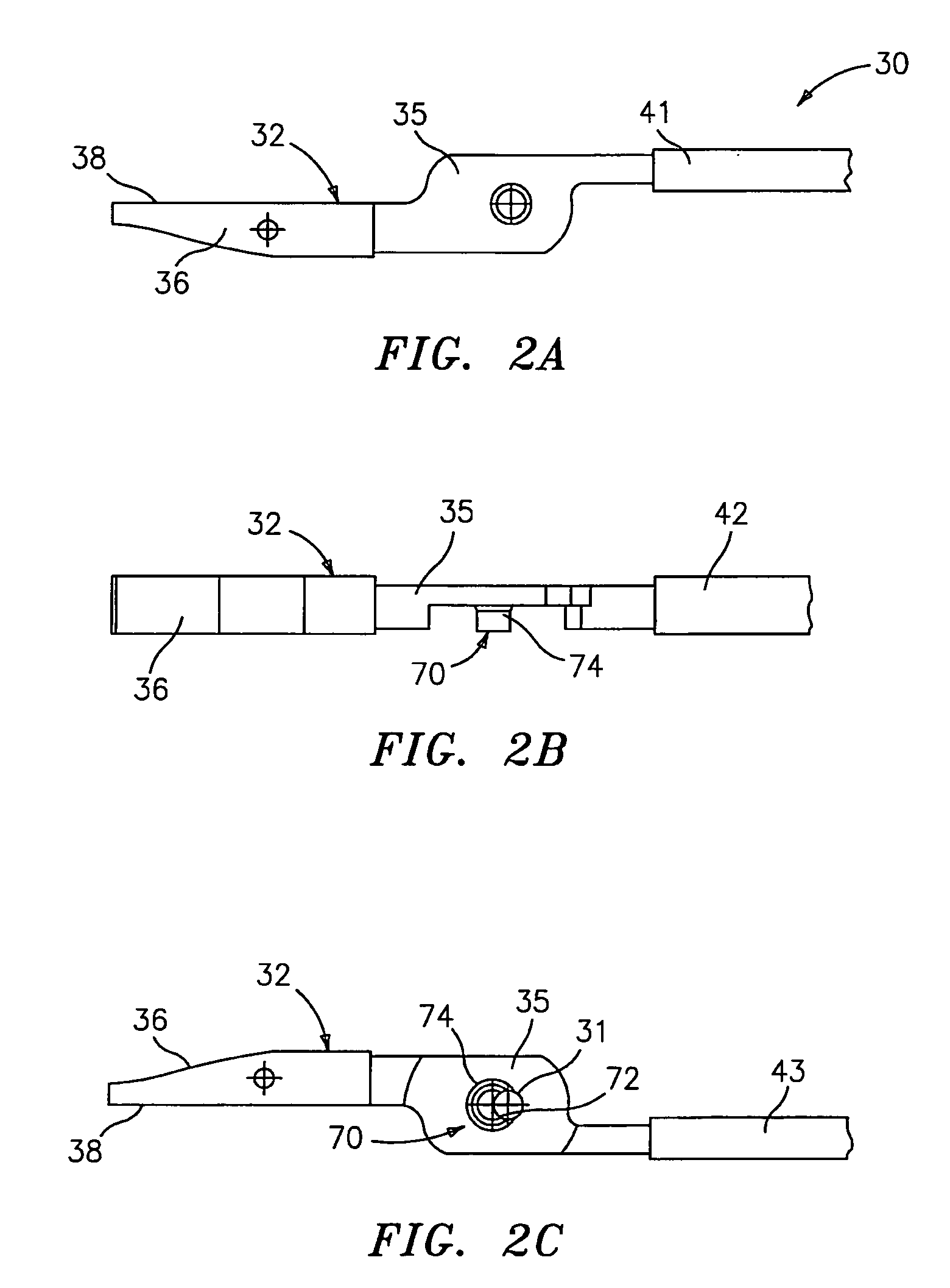
[0023] Referring now in specific detail to the drawings in which like reference numerals identify similar or identical elements throughout the several views, and initially to FIGS. 1-3C, one particular embodiment of an electrosurgical instrument 10 includes two elongated shafts 30 and 60 each having a distal end effector 32, 62 and a proximal handle portion 34 and 64, respectively. Handles 34 and 64 are movable relative to one another about a hinge assembly 20 from a first position wherein the distal end effectors 32, 62 are positioned in spaced relation relative to one another to a second position in which the distal end effectors 32, 62 cooperate to grasp tissue therebetween. It is envisioned that handles 34 and 64 may take any design configuration suitable for manipulation or control of the surgical instrument 10.

[0024] Each distal end, e.g., 32, has a jaw member 36 disposed at the distal end thereof which includes a tissue grasping surface 38 dimensioned to cooperate with the o...


PUM

PropertyMeasurementUnit
specific gap distanceaaaaaaaaaa
Comparative Tracking Indexaaaaaaaaaa
thicknessaaaaaaaaaa

Abstract

An electrosurgical instrument includes a pair of first and second elongated shafts each having an end effector attached to a distal end thereof and a handle. The handle is movable from a first position wherein the end effectors are disposed in spaced relation relative to one another to a second position wherein the end effectors are closer relative to one another. Each of the elongated shafts includes a hinge plate which mounts atop a pivot assembly for effecting movement of the end effectors relative to one another. The instrument also includes a hinge assembly made from an overmold composition which encapsulates and secures the hinge plates and the pivot assembly. The overmold composition is made from an electrically insulating material which insulates the end effectors from one another.

Description

CROSS REFERENCE TO RELATED APPLICATION [0001] This application claims the benefits of and priority to U.S. Provisional Patent Application Ser. No. 60 / 281,924 entitled: “MOLDED INSULATING HINGE FOR BIPOLAR INSTRUMENT” which was filed on Apr. 6, 2001 by Sartor et al., the entire contents of this application are hereby incorporated by reference herein.BACKGROUND [0002] 1. Technical Field [0003] The present disclosure relates to joints and hinges which connect movable components of an electrosurgical instrument and methods for fabricating hinges for movable components of an electrosurgical instrument. More particularly, the present disclosure relates to an easily customizable hinge made from a plastic overmold composition which connects two end effectors for relative movement therebetween. The present disclosure also relates to a method for fabricating the overmolded hinge. [0004] 2. Background of Related Art [0005] Typically, joints and hinges for electrosurgical instruments which conn...

Claims


Application Information

Patent Timeline
Patent Type & Authority Applications(United States)
IPC IPC(8): A61B18/04A61B17/28A61B18/14A61B18/12
CPCA61B18/1445A61B2017/2939Y10T29/4998Y10T29/49888Y10T29/24A61B2018/126
Inventor SARTOR, JOE DONHARVILLA, DENNIS J.
Owner COVIDIEN AG
Learn More