Rack for bicycles

a bicycle rack and rack technology, applied in the field of bicycle racks, can solve the problems of inconvenience and the number of bicycles to use this conventional rack

Inactive Publication Date: 2006-11-30
TSAI DAVID
View PDF11 Cites 31 Cited by
  • Summary
  • Abstract
  • Description
  • Claims
  • Application Information

AI Technical Summary

Benefits of technology

[0006] According to the present invention, a rack is disclosed for regulating the parking of bicycles. The rack includes a base that provides flexibility in length and at least one pair of restraints installed on the base.

Problems solved by technology

A problem with the rack 1 is that the number of bicycles that can be restrained is determined when the length of the tracks 3 is set.
Another problem with the rack 1 is the inconvenience to use this conventional rack since a wheel of a bicycle can only be put between a pair of restraints from the gap between the inclined portions 112 of the arched bones 11.

Method used


Image

  • Rack for bicycles
  • Rack for bicycles
  • Rack for bicycles

Examples


Embodiment Construction

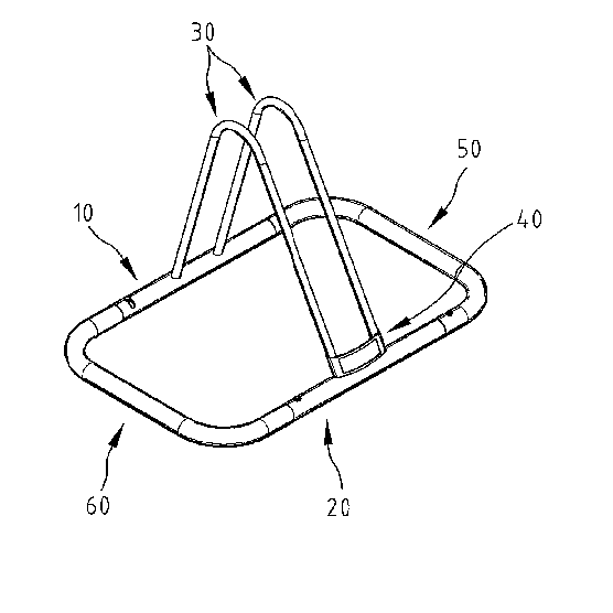
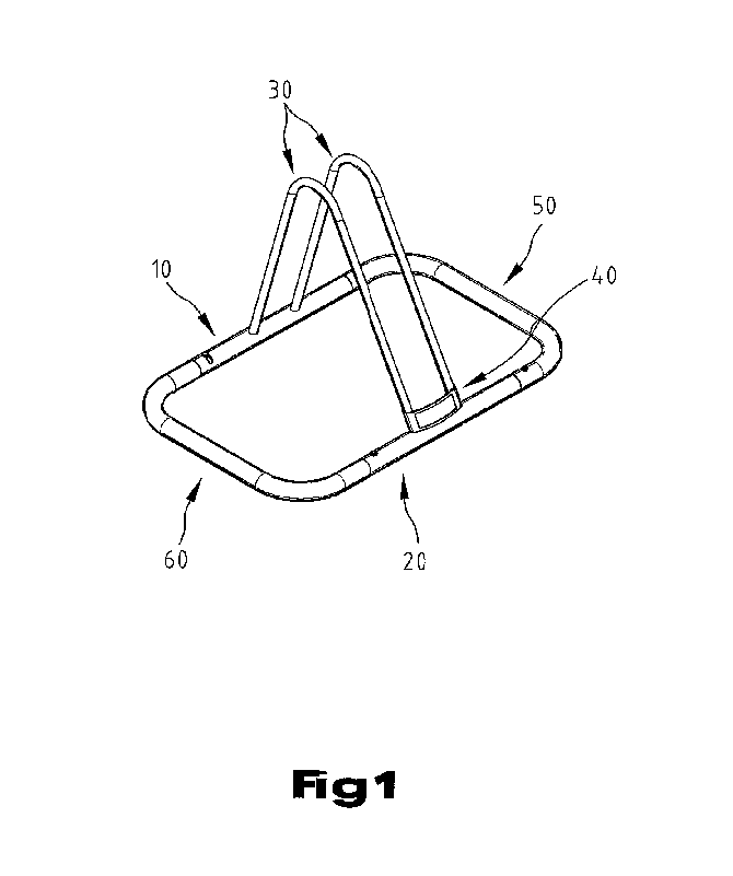
[0015] Referring to FIGS. 1 and 2, according to a first embodiment of the present invention, a rack includes a base and a pair of inverted V-shaped bones 30 installed on the base. The base is a frame consisting of a first transverse tube 10, a second transverse tube 20, a first lateral tube 50 and a second lateral tube 60.

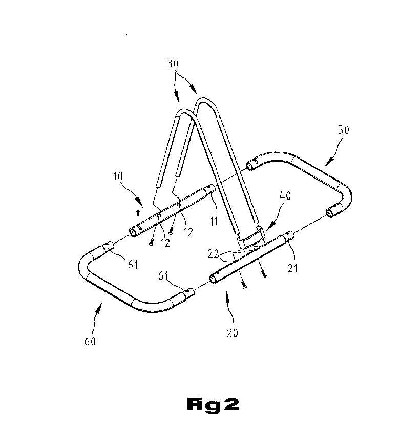
[0016] The first transverse tube 10 includes a reduced end 111. In the first transverse tube 10 are defined two apertures 12 each for receiving an end of an inverted V-shaped bone 30.

[0017] The second transverse tube 20 includes a reduced end 21. In the second transverse tube 20 are defined two apertures 22 each for receiving an end of an inverted V-shaped bone 30.

[0018] The first lateral tube 50 includes a central portion put perpendicular to the first transverse tube 10 and the second transverse tube 20 and two ends put parallel to the same. The reduced end 11 of the first transverse tube 10 is inserted in an end of the first lateral tube 50. The reduced end 2...


PUM


Abstract

A rack is disclosed for regulating the parking of bicycles. The rack includes a base that provides flexibility in length and at least one pair of restraints installed on the base. The base includes a first lateral tube, a second lateral tube and at least one pair of transverse tubes. The first lateral tube includes a central portion and two ends extending from the central portion. The second lateral tube includes a central portion and two ends extending from the central portion. Each transverse tube includes a first end connected to one of the ends of the first lateral tube and a second end connected to one of the ends of the second lateral tube. The pair of restraints is installed on the pair of transverse tubes.

Description

BACKGROUND OF INVENTION [0001] 1. Field of Invention [0002] The present invention relates to bicycles and, more particularly, to a rack for bicycles in order to regulate the parking of the bicycles. [0003] 2. Related Prior Art [0004] As disclosed in Taiwanese Patent Publication No. 496336, a rack 1 includes two tracks 3 anchored to the ground or a floor and a pair of restraints secured to the tracks 3 by means of a plurality of fasteners 2. A plurality of slots 31 is defined in each track 3. Each restraint includes a straight bone 12 and an arched bone 11 formed on the straight bone 12. The straight bones 12 are connected to each other by means of two mounts 13. The mounts 13 are connected to the straight bones 12 through soldering. Two slots 131 are defined in each mount 13. The fasteners 2 are inserted through some of the slots 31 and the slots 131 in order to install the pair of restraints on the tracks 3. Each arched bone 11 includes a vertical portion 111 and an inclined portio...

Claims


Application Information

Patent Timeline
Patent Type & Authority Applications(United States)
IPC IPC(8): A47F7/00
CPCB62H3/00
Inventor TSAI, DAVID
Owner TSAI DAVID
Why Eureka
Try Eureka