Sensor package for WIM sensor and WIM sensor

a wim sensor and sensor technology, applied in the direction of measuring devices, instruments, weighing apparatus, etc., can solve the problems of difficult to meet the requirements, difficult to produce steel receiving plates in the desired length from one to several meters, and the required thickness is extremely difficult, so as to reduce the need for product variety, simplify assembly, and flexible sensor length

Active Publication Date: 2016-06-21
KISTLER HLDG AG
View PDF40 Cites 7 Cited by
  • Summary
  • Abstract
  • Description
  • Claims
  • Application Information

AI Technical Summary

Benefits of technology

[0015]Another significant advantage of the invention is the flexibility in the length of the sensor, since the receiving elements, which are now shorter, can be assembled to the desired length. This reduces the need for product variety and simplifies assembly. It is also possible to build WIM sensors of different lengths, even longer than 2 m, which was not previously possible.
[0016]Further variations of the invention are described in greater detail below.

Problems solved by technology

The production of steel receiving plates in the desired length from one to several meters and the required thickness is extremely difficult.
The required surface tolerances such as flatness, parallelism, thickness, surface roughness, etc., as the quartz receiving can only be obtained by employing a grinding process that is almost impossible for such lengths, and at all events involves huge effort.
The receiving plates are prone to bending and twisting.
It has been found that the construction is very complicated, because each element must be manufactured, tensioned and sealed individually.
Since the WIM sensors are also exposed to environmental influences in the street, the seal loses its sealing quality after a certain time, leading to the failure of individual sensors.
It has proven difficult to insert the sensor elements in the closed tube.

Method used


Image

  • Sensor package for WIM sensor and WIM sensor
  • Sensor package for WIM sensor and WIM sensor
  • Sensor package for WIM sensor and WIM sensor

Examples


Embodiment Construction

[0024]In the following, the invention will be described in greater detail with reference to the figures. The same reference numerals will be used consistently to refer to the same items.

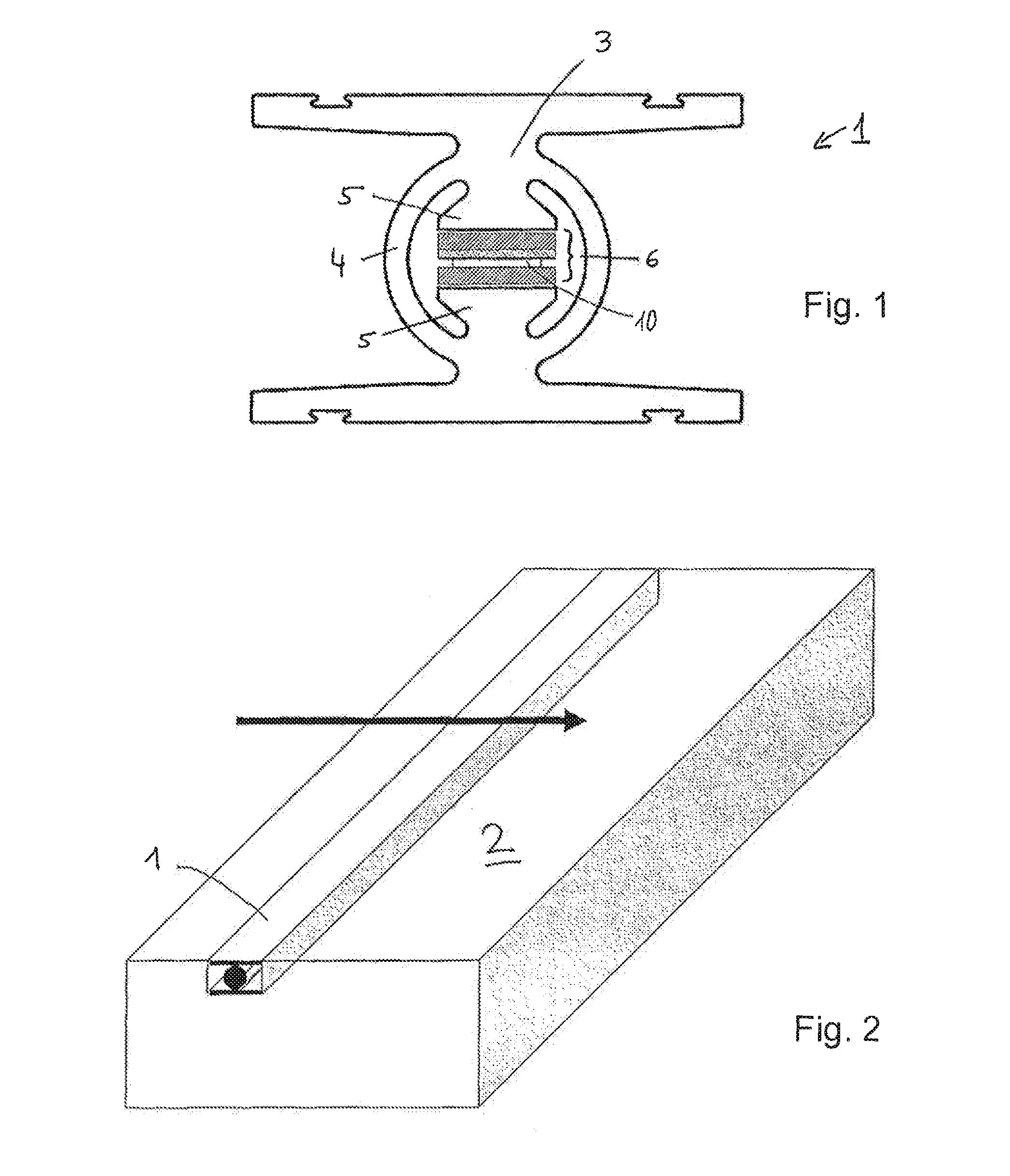
[0025]In FIG. 1, a hollow profile 3 of a WIM (Weigh in Motion) sensor 1 is shown in cross section. The height and width of such hollow profiles 3 are usually between 30 and 70 mm, while the length thereof, not shown here, is typically between 1 m and 4 m. Consequently, such hollow profiles 3 may be described as long in comparison to the cross-sectional dimensions thereof.

[0026]Hollow profile 3 comprises a central tube 4 and two mountings 5 arranged opposite one another inside the tube. A sensor package 6 is clamped between said mountings 5. Tube 4 ensures that the initial tension is exerted uniformly on sensor package 6 and that sensor package 6 is sealed over the entire length of WIM sensor 1. In operation, a force is absorbed by hollow profile 3 from the outer, non-designated plates and transferred...


PUM


Abstract

The invention relates to a sensor package (6) with long design for a WIM (Weigh in Motion) sensor (1), comprising a first receiving plate (7), a plurality of measuring elements (10), which are arranged equally spaced in a row (15) on the upper side (9) of the first receiving plate (7), an electrode (11) covering all the measuring elements (10), insulation (12) completely covering the electrode (11), and a second receiving plate (8), which covers the insulation (12). In particular, each receiving plate (7, 8) consists of a plurality of receiving elements (13) the end faces (14) of which are juxtaposed in a row (15). According to the invention, the inner end faces (14) of the receiving elements (13) of at least one row (15) have profiles (16) which engage in a form fit manner with the profiles (16) of the adjacent end faces (14) of neighboring receiving elements (13). The invention further relates to a WIM sensor (1) comprising a hollow profile (3) with a tube (4) and two opposing mountings (5) arranged therein, between which a sensor package (6) according to the invention is arranged under initial tension.

Description

CROSS-REFERENCE TO RELATED APPLICATIONS[0001]This application claims priority to International Application Serial No. PCT / CH2013 / 000005, filed Jan. 11, 2013, which claims priority to Swiss Application No. 47 / 12 filed Jan. 11, 2012. International Application Serial No. PCT / CH2013 / 000005 is hereby incorporated herein for all purposes by this reference.FIELD OF THE INVENTION[0002]The invention relates to a sensor package with long design for a WIM (Weigh In Motion) sensor comprising a first receiving plate, a plurality of measuring elements which are arranged equally spaced in a row on the upper side of the first receiving plate, an electrode covering all the measuring elements, insulation completely covering the electrode, and a second receiving plate which covers the insulation, wherein each receiving plate consists of a plurality of receiving elements, the end faces of which are juxtaposed in a row.BACKGROUND[0003]WIM sensors are sensors between one and several meters long that are ...

Claims


Application Information

Patent Timeline
Patent Type & Authority Patents(United States)
IPC IPC(8): G01G19/02G01G21/28G01G3/13
CPCG01G3/13G01G19/024G01G21/28
Inventor CORNU, DAVIDHOFMANN, ADRIANFREI, PETER
Owner KISTLER HLDG AG
Why Eureka
Try Eureka