
Iced beverage dispensing tower

Inactive Publication Date: 2006-12-07
PENTAIR FLOW SERVICES
View PDF12 Cites 18 Cited by
  • Summary
  • Abstract
  • Description
  • Claims
  • Application Information

AI Technical Summary

Benefits of technology

[0008] Other iced beverage towers have now been invented. New ways of making the tower so that it can be cooled to the point of being iced-over make it possibl

Problems solved by technology

The beverage, being predominantly water, had a tendency to freeze and plug up the beverage supply line when no beverage was bein

Method used


Image

  • Iced beverage dispensing tower
  • Iced beverage dispensing tower
  • Iced beverage dispensing tower

Examples


Example

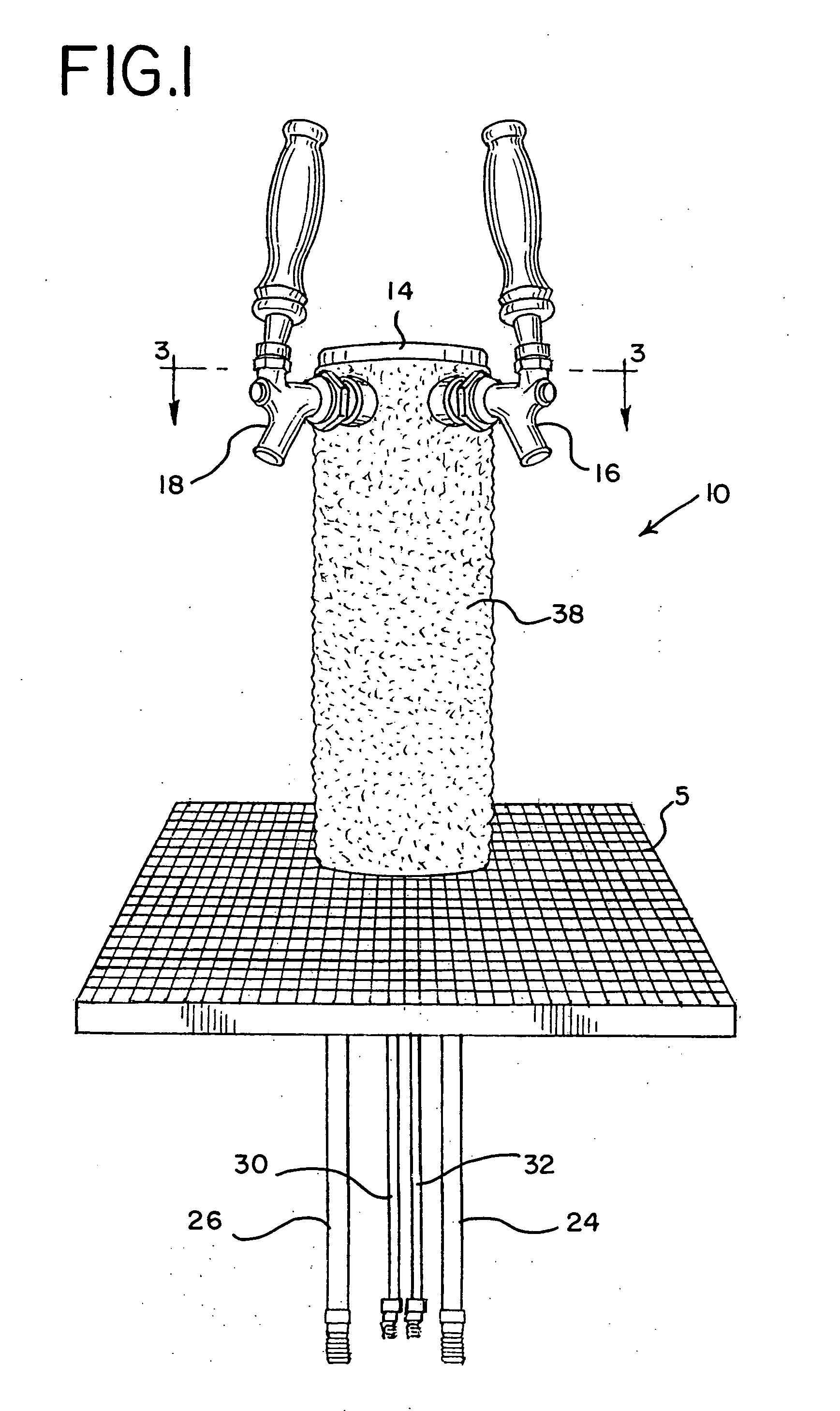
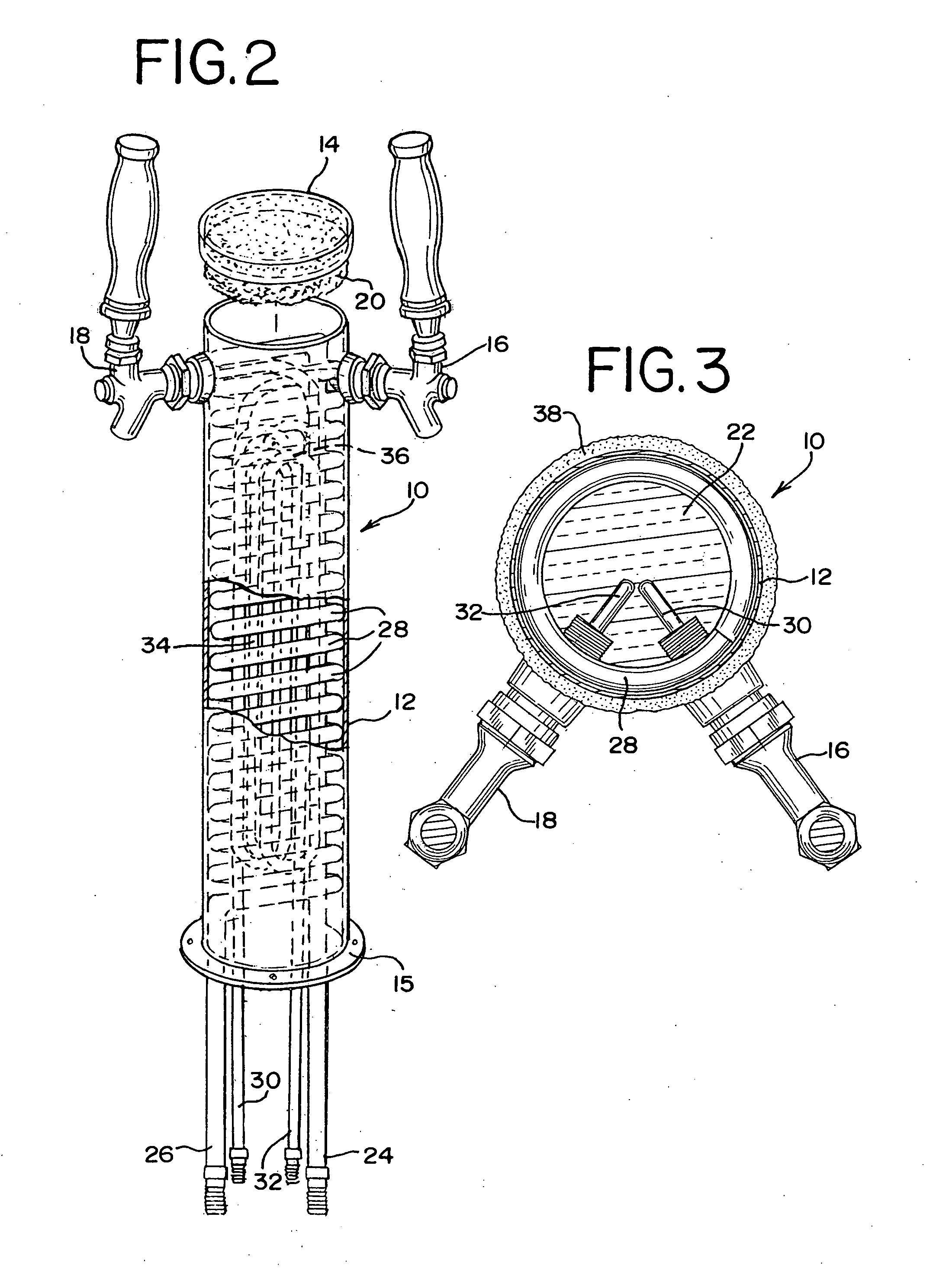
[0031] A first embodiment of an iced beverage dispensing tower 10 of the present invention is shown in FIGS. 1-3. The tower 10 is shown as part of a beverage serving system that also includes a countertop having a drain surface 5. The beverage dispensing tower is upstanding from the countertop. This of course is part of a beverage dispensing system, which includes not only the beverage dispensing tower but a beverage supply connected to the beverage serving system by a beverage line. For a complete description of the remainder of a typical beverage dispensing system, attention is drawn to U.S. Pat. No. 6,487,873, which is incorporated herein by reference.

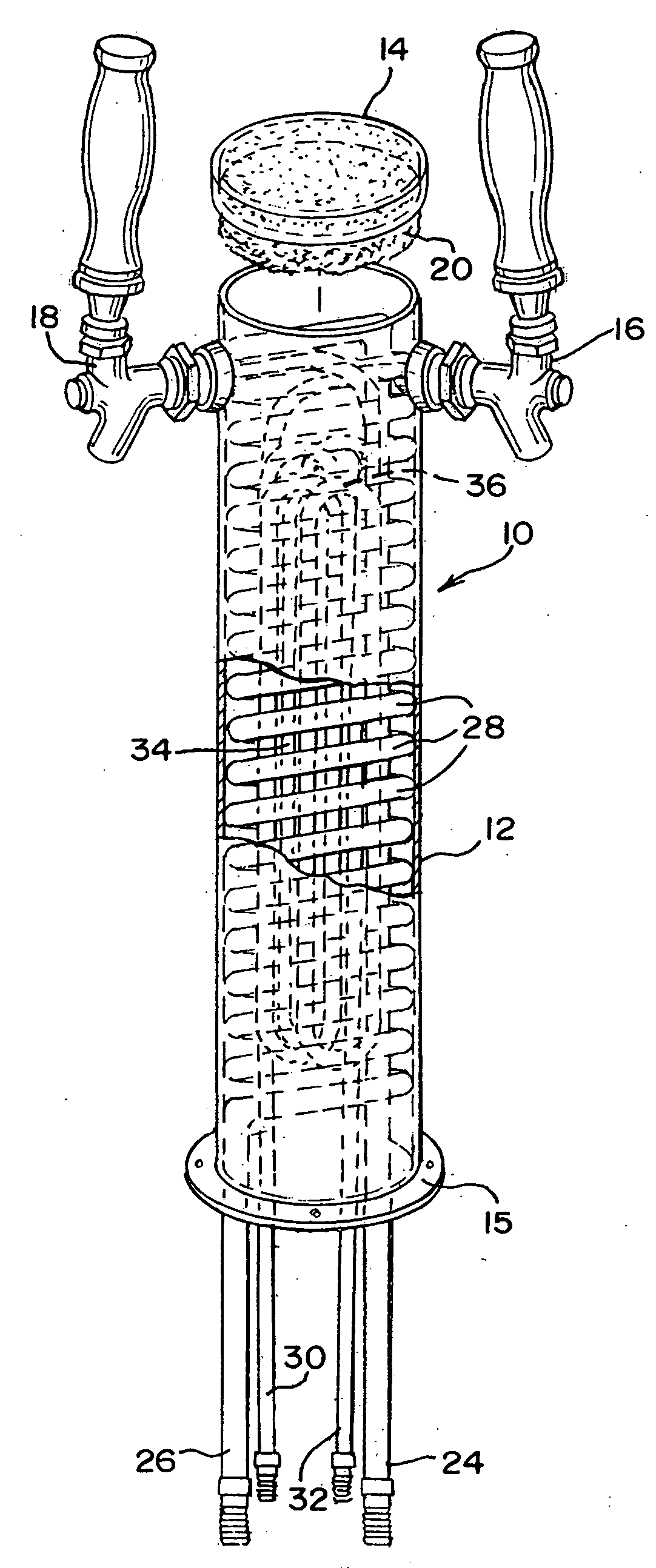
[0032] In FIGS. 1 and 3, the tower 10 is shown as an iced-over beverage dispensing tower. FIG. 2 shows the components of the tower 10 without any frost icing over the tower. The beverage dispensing tower 10 has a housing 12 comprising a cylindrical base and two beverage dispensing taps 16 and 18 mounted on the housing 12. In this e...

Example

[0036] A third embodiment of an iced beverage dispensing tower 60 is shown in FIGS. 6 and 7. Again, the tower 60 is shown as part of a beverage serving system. A drain surface 65 is provided on the countertop around the base of the tower and under the dispensing tap 66.

[0037]FIG. 6 shows a casting 62 used to make the tower 60. The casting is preferably metal, and includes tubing 64 encased in the casting. Thus, in this embodiment the confined cooling channel comprises a plurality of channels formed in a wall section of the housing. The tubing 64 has an inlet 72 and an outlet 74 attached to it before it is encased in the casting. The inlet and outlet may include fittings that are encased in the metal used for the casting but have exposed threads to which glycol coolant lines can be attached. The tubing 64 preferably includes a plurality of loops inside the casting. In the embodiment shown, the tubing includes two Tee connections and two U-shaped loops. Of course other tubing configu...


PUM


Abstract

A beverage dispensing tower includes an exterior surface; at least one beverage dispensing tap and a beverage supply line connected thereto; and a coolant flow path in sufficient thermal contact with the exterior surface so that as coolant flows through the flow path, at least part of the exterior surface can be cooled to a temperature below 32° F. when the dispensing tower is in contact with air having and ambient temperature of 68° F., the coolant flow path not being in direct contact with the beverage supply line.

Description

RELATED APPLICATION [0001] The present application claims the benefit under 35 U.S.C. § 119(e) of Provisional U.S. Patent Application Ser. No. 60 / 683,396, filed May 20, 2005; which is hereby incorporated by reference in its entirety.BACKGROUND OF THE INVENTION [0002] The present invention relates to beverage dispensing equipment, and particularly to a beverage dispensing tower which may become iced-over when in use. [0003] Beverage dispensing equipment often fulfills not only a functional role, but an aesthetic role as well. In an establishment where beverages are served, the beverage dispensing equipment is often in an area where members of the public see the dispensing equipment. One particular type of beverage dispensing equipment that fits into this category is beverage dispensing towers. Beer dispensing towers are a good example. Such towers are often located on a countertop, such as a bar. Owners of the establishment wish to present a pleasing aesthetic appearance to members o...

Claims


Application Information

Patent Timeline
IPC IPC(8): B67D5/62B67D7/80
CPCB67D1/0872B67D1/0858B67D1/06
Inventor KYEES, MELVIN D.KYEES, RICHARD O.
Owner PENTAIR FLOW SERVICES
Learn More