Video quality evaluation device, video quality evaluation method, video quality evaluation program, video matching device, video aligning method and video aligning program

Active Publication Date: 2006-12-07
NIPPON TELEGRAPH & TELEPHONE CORP
View PDF6 Cites 35 Cited by
  • Summary
  • Abstract
  • Description
  • Claims
  • Application Information

AI Technical Summary

Benefits of technology

[0016] In consideration of the conventional techniques mentioned above, an object of the present invention is to provide a video quality assessing apparatus, a vi

Problems solved by technology

Video information generally deteriorates its quality when subjected to some process such as encoding or transmitting through a network.
Assessing a quality of video images by actually watching the video images with human eyes is laborious and takes a long time.
Feature values employed by this method, however, are insufficient to provide an assessment accuracy comparable to that of a subjective assessment by human.
These services involve a risk of losing information pieces such as packets.
It is difficult, therefore, to align spatial positions betwe

Method used


Image

  • Video quality evaluation device, video quality evaluation method, video quality evaluation program, video matching device, video aligning method and video aligning program
  • Video quality evaluation device, video quality evaluation method, video quality evaluation program, video matching device, video aligning method and video aligning program
  • Video quality evaluation device, video quality evaluation method, video quality evaluation program, video matching device, video aligning method and video aligning program

Examples


first embodiment

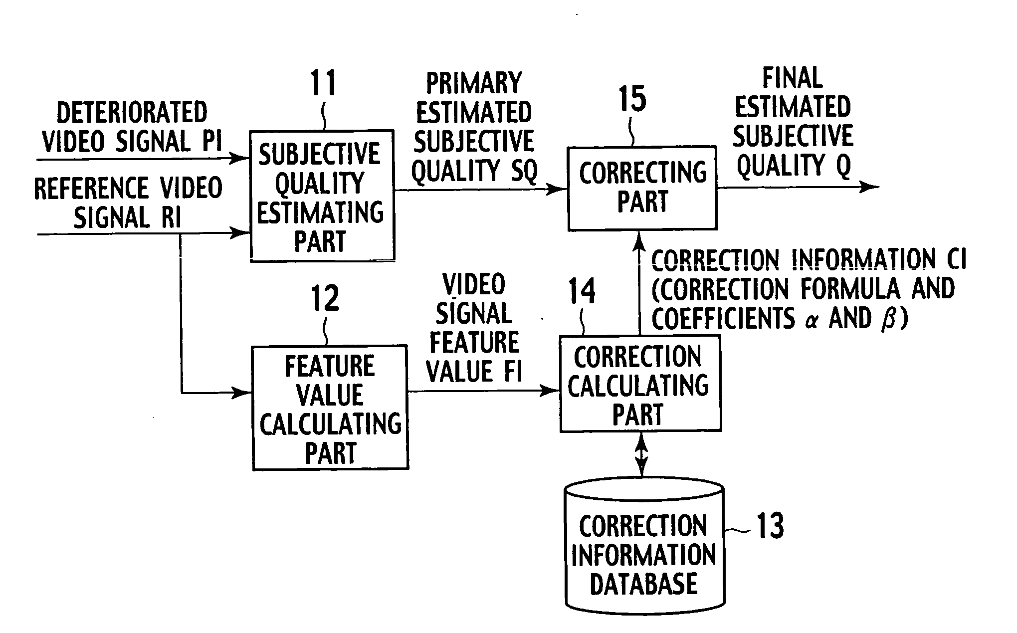
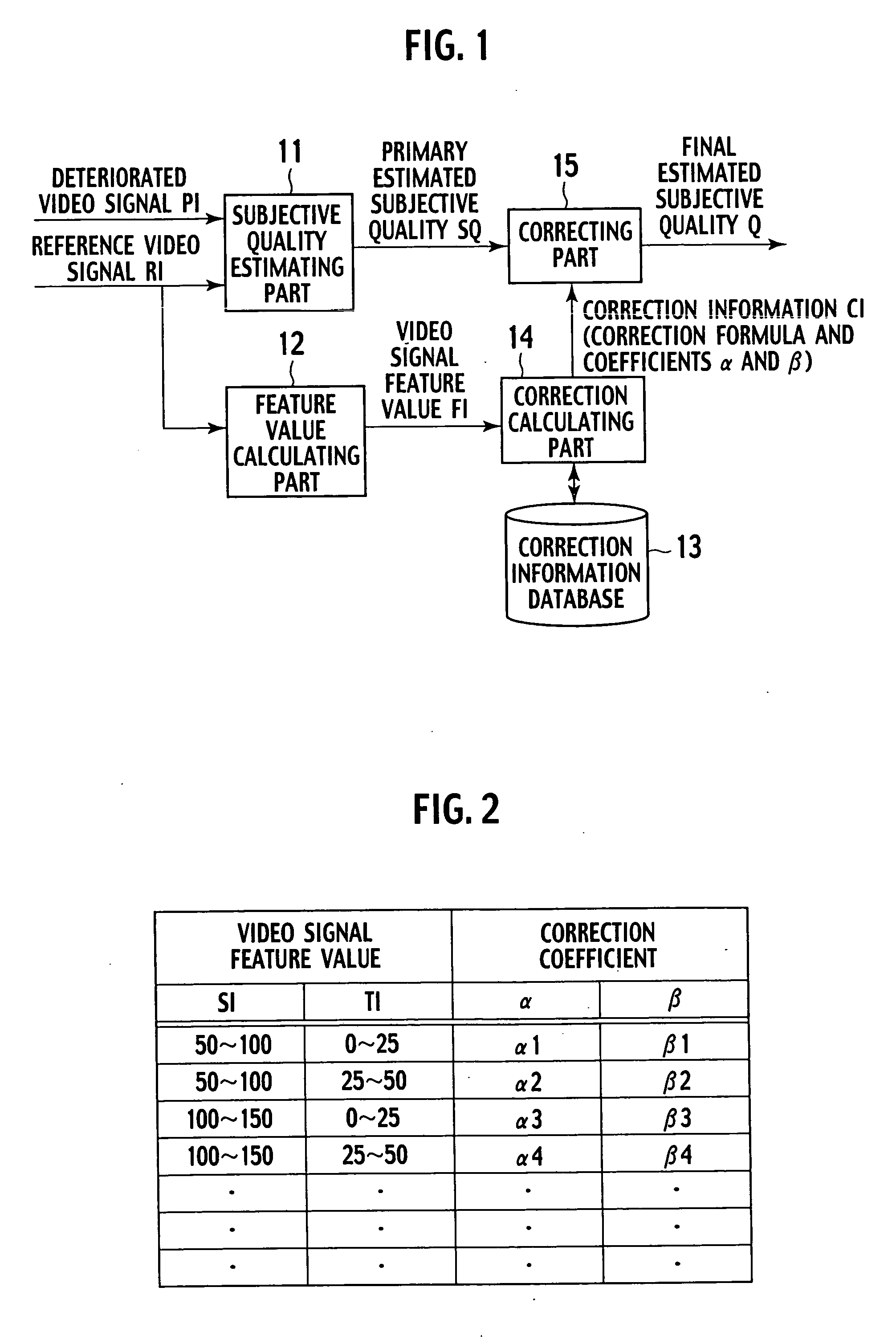
[0076] The video quality assessing apparatus according to the first embodiment of the present invention will be explained with reference to FIG. 1. FIG. 1 is a block diagram showing the video quality assessing apparatus according to the first embodiment of the present invention.

[0077] The video quality assessing apparatus of the first embodiment at least includes a subjective quality estimating part 11, a feature value calculating part 12, a correction information database 13, a correction calculating part 14, and a correcting part 15.

[0078] The subjective quality estimating part 11 receives an undeteriorated reference video signal RI and a deteriorated video signal PI. The deteriorated video signal PI is produced from the reference video signal RI through, for example, encoding or network transmission.

[0079] For the reference video signal RI and deteriorated video signal PI, the subjective quality estimating part 11 calculates a difference between physical feature values of the ...

second embodiment

[0094] Components of a video quality assessing apparatus according to the second embodiment of the present invention will be explained with reference to FIG. 4. FIG. 4 is a block diagram showing an arrangement of the video quality assessing apparatus according to the second embodiment of the present invention.

[0095] In FIG. 4, the video quality assessing apparatus according to the second embodiment has an alignment information generating part 21, a spatial feature value calculating part 22, a temporal feature value calculating part 23, and a subjective quality estimating part 24.

[0096] The alignment information generating part 21 receives a reference video signal RI and a deteriorated video signal PI, extracts reference video frames from the reference video signal RI and deteriorated video frames from the deteriorated video signal PI, detects temporal and spatial deviations between the reference and deteriorated video frames, and generates alignment information concerning the temp...

third embodiment

[0128] Components of a video quality assessing apparatus according to the third embodiment of the present invention will be explained with reference to FIG. 6. FIG. 6 is a block diagram showing an arrangement of the video quality assessing apparatus according to the third embodiment of the present invention.

[0129] Compared with the video quality assessing apparatus of the second embodiment, the video quality assessing apparatus of the third embodiment differs in that it receives a reference video signal RI and deteriorated video signal PI having different file formats and in that a signal format of the deteriorated video signal PI, an information size of deteriorated video images transmitted with the deteriorated video signal PI, and an encoding system of the deteriorated video signal are unknown. The same parts as those of the video quality assessing apparatus of the second embodiment are represented with like reference marks and their explanations are omitted.

[0130] The video qu...


PUM


Abstract

A subjective quality estimating part (11) receives an undeteriorated reference video signal (RI) and a deteriorated video signal (PI) produced from the reference video signal, calculates video signal feature values for both the signals, and according to a difference between the calculated video signal feature values of the signals, estimates a subjective quality of the deteriorated video signal. A feature value calculating part (12) calculates the video signal feature values of the reference video signal. A correction information storing part (13) stores correction information that corresponds to video signal feature values and is used to correct the subjective quality. A correction calculating part (14) receives the video signal feature values of the reference video signal from the feature value calculating part (12), retrieves correction information corresponding to the received video signal feature values from the correction information storing part (13), and transfers the retrieved correction information to a correcting part (15). According to the transferred correction information, the correcting part (15) corrects the subjective quality estimated by the subjective quality estimating part (11).

Description

TECHNICAL FIELD [0001] The present invention relates to a video quality assessing apparatus, a video quality assessing method, and a video quality assessing program that estimate a subjective quality of video images by measuring the physical feature values of a video signal without conducting a subjective quality assessing test in which a human tester actually watches the video images and assesses a quality thereof. [0002] The present invention also relates to a video aligning apparatus, a video aligning method, and a video aligning program that work with the video quality assessing apparatus, video quality assessing method, and video quality assessing program and spatially and temporally align a deteriorated video signal with a reference video signal, the deteriorated video signal being produced by encoding or transmitting through, for example, a network the reference video signal. BACKGROUND ART [0003] Video information generally deteriorates its quality when subjected to some pro...

Claims


Application Information

Patent Timeline
IPC IPC(8): G01R29/26H04N17/00
CPCH04N17/04H04N17/00
Inventor OKAMOTO, JUNKURITA, TAKAAKI
Owner NIPPON TELEGRAPH & TELEPHONE CORP
Why Eureka
Try Eureka