Process and apparatus for generating and delivering an enriched gas fraction

US20060288869A1Inactive Publication Date: 2006-12-28WEARAIR OXYGEN

Image

  • Process and apparatus for generating and delivering an enriched gas fraction
  • Process and apparatus for generating and delivering an enriched gas fraction
  • Process and apparatus for generating and delivering an enriched gas fraction

Examples


Embodiment Construction

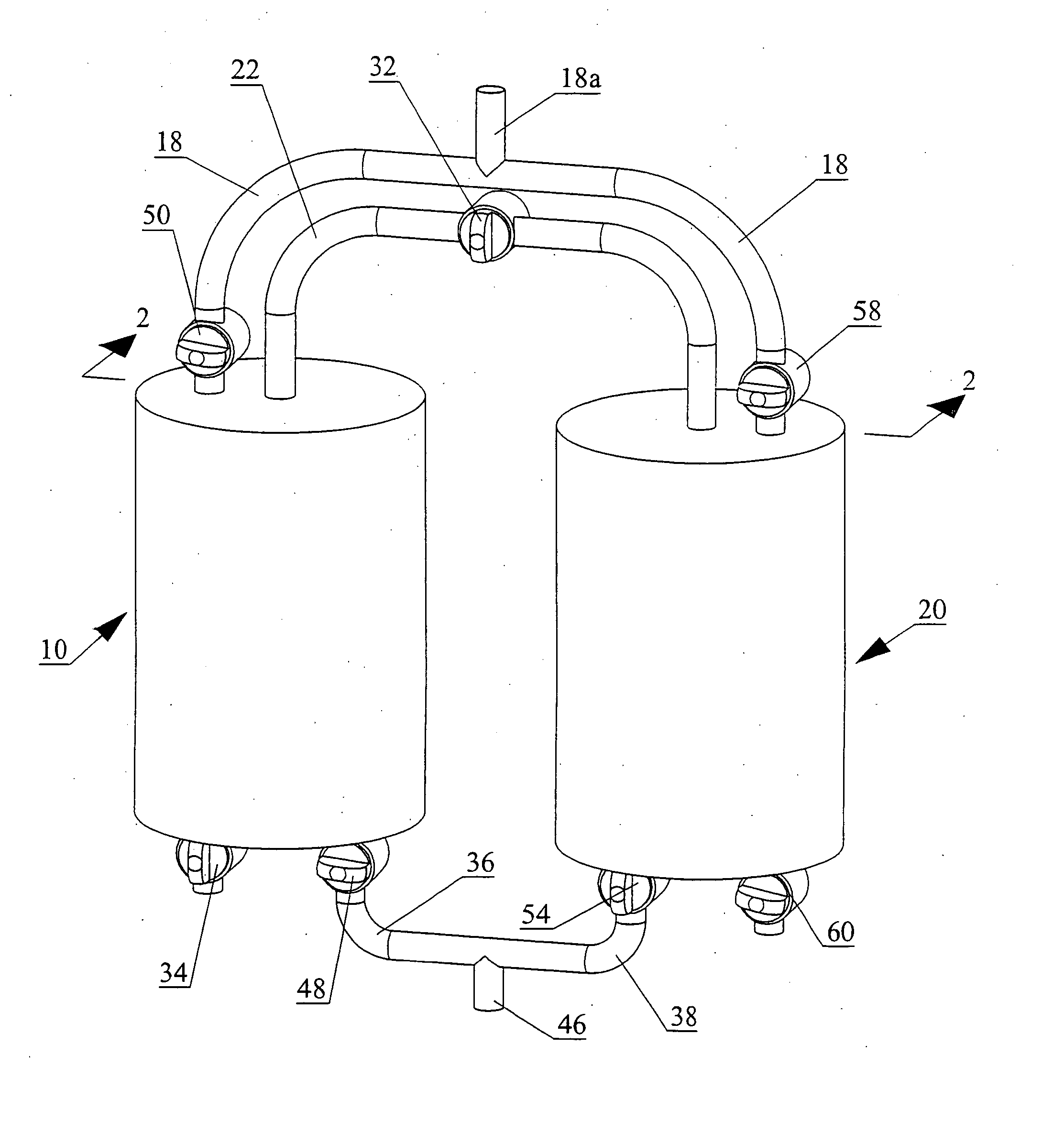
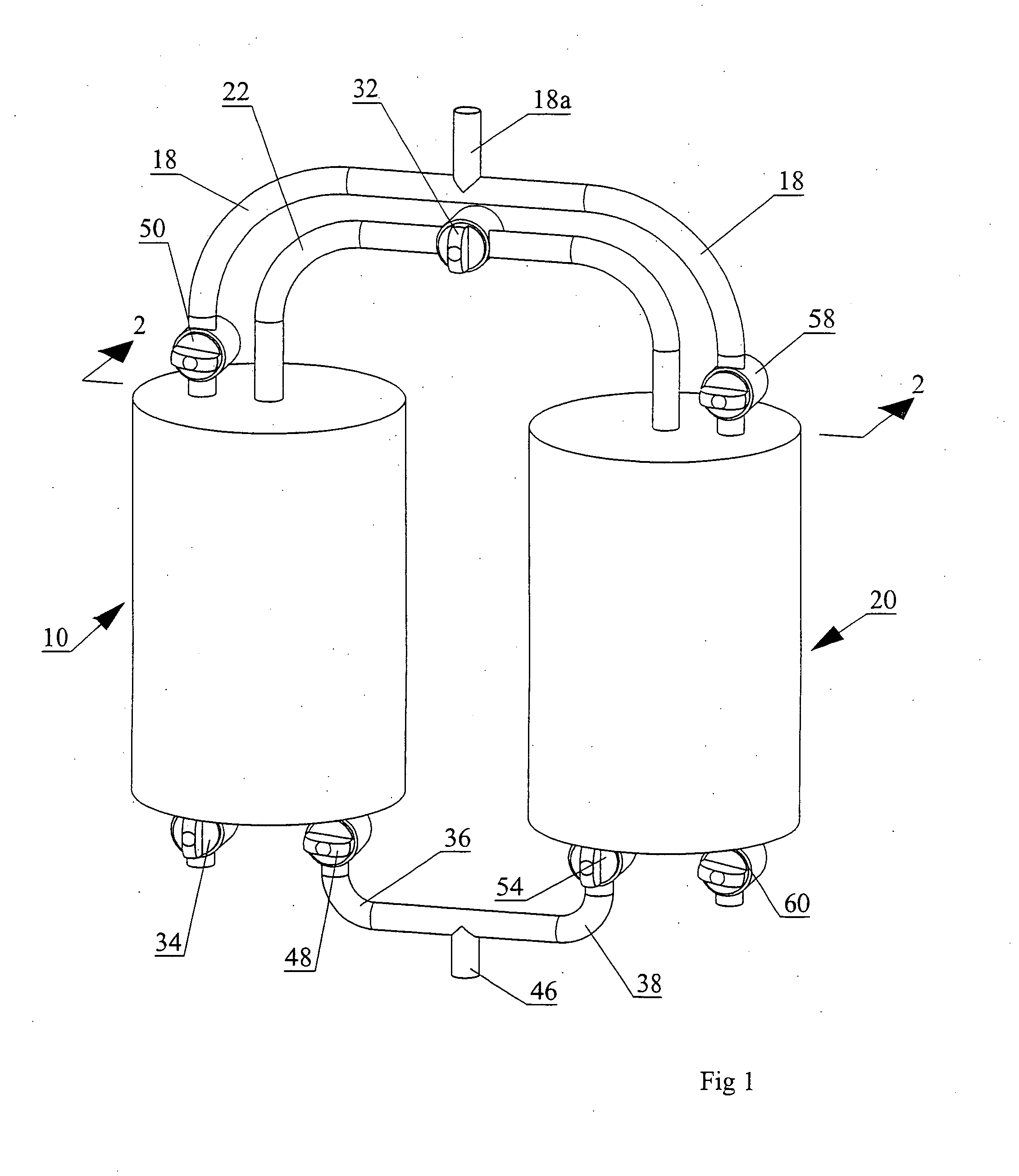
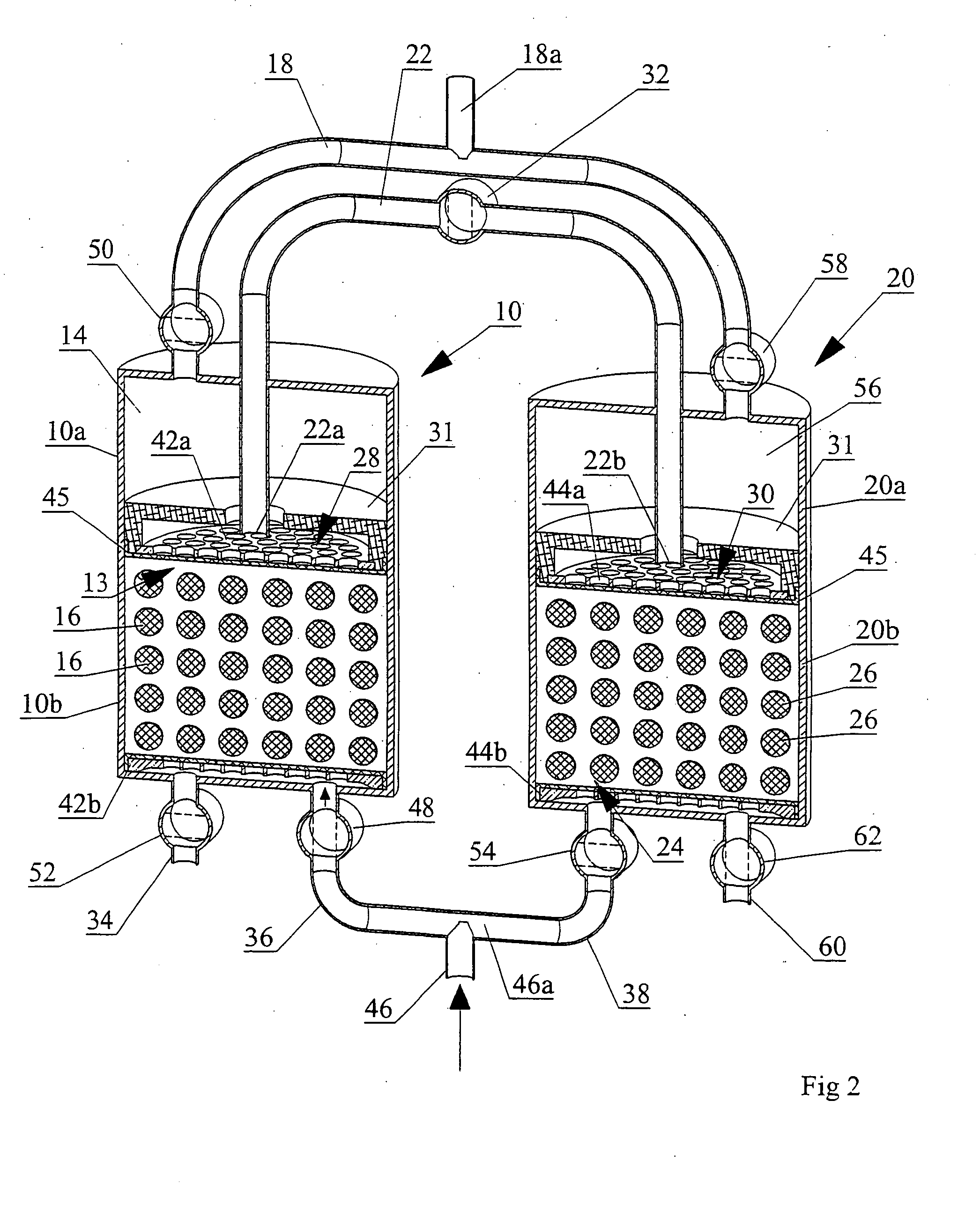
[0097] The mechanics of a one half-cycle will now be described.

[0098] In the present invention, wherein like reference numerals denote corresponding parts in each view, a first container is pressurized with air by a compressor (shown in FIG. 3). Advantageously, the first container contains a high mole fraction of oxygen and is pressurized with atmospheric air. Nitrogen will adsorb to the zeolite more readily than oxygen. As a result there will be a higher concentration of oxygen in the zeolite void space and the product end void space than there was in the original air mixture. Ensuring the starting oxygen mole fraction is high can produce high oxygen concentration end use gas. This ensures effectively all the nitrogen from atmospheric pressurization can be adsorbed by the zeolite.

[0099] Some of the product end void space gas is then released for end use from the first container.

[0100] When a gas mixture is vented from any pressurized zeolite container, the oxygen enriched zeolit...


PUM

PropertyMeasurementUnit
Fractionaaaaaaaaaa
Pressureaaaaaaaaaa
Massaaaaaaaaaa

Abstract

An improved sieve bed design to manage breakthrough and the mass transfer zone by way of volumetric division. An empty space in the product end is separated from adsorbent-filled sieve space in the feed end by a mid-diffuser plate. The ratio of the empty product end void space to the adsorbent filled sieve space within a sieve bed may be determined by the relative percentages of the gasses to be separated and the bulk loading factor of the molecular sieve. A product end void space of the correct volume may ensure the maximum volume of nitrogen has been adsorbed before breakthrough occurs. In operation, pressure in the sieve bed empty space and sieve filled space may be equal at any instant. This contains breakthrough to the location of the mid-diffuser plate. The mass transfer zone may be static at the point of the mid-diffuser plate and as such, gas separation is a function of pressure within the bed.

Description

CROSS-REFERENCE TO RELATED APPLICATIONS [0001] This application claims benefit of provisional application Ser. No. 60 / 693,920 filed on Jun. 27, 2005.FIELD OF THE INVENTION [0002] This invention relates to the field of gas concentrators and gas conserving devices. BACKGROUND OF THE INVENTION [0003] The process of pressure swing adsorption (PSA) to enrich the concentration of a gas, such as the oxygen concentration, is known in the prior art. The challenge has been to generate sufficient quantities or flow rates of the enriched gas, in a sufficiently high concentration, to enable the therapeutic use of a PSA machine. A further challenge has been to make such a machine portable, that is relatively small and lightweight, self-sufficient, and self contained for realistic portability by a patient over an extended period of time. [0004] It is also known in the prior art to attempt to conserve the target gas using an oxygen conserving device (OCD), that is, conserve the use of for example h...

Claims


Application Information

Patent Timeline
28 Dec 2006
Publication
US20060288869A1
IPC
B01D53/02
CPC
B01D53/0407; B01D53/0446; B01D53/0454; B01D53/047; B01D2253/108; B01D2253/304; B01D2259/4533; B01D2257/102
Inventors
WARREN, JOHN L.; HISCOCK, ANTHONY