Radiant gas burner

Inactive Publication Date: 2006-12-28
A V LUIKOV HEAT & MASS TRANSFER INST OF THE NAT ACADEMY OF SCI OF BELARUS
View PDF6 Cites 27 Cited by
  • Summary
  • Abstract
  • Description
  • Claims
  • Application Information

AI Technical Summary

Benefits of technology

[0011] A radiant gas burner is provided including a casing adapted for connection with an air-gas mixing and supply system having a flux dissector and a mixer. The burner further includes a metallic mesh emitter, inside the casing, having lower and upper meshes. The lower mesh and t

Problems solved by technology

One of the shortcomings of this type of burner is that the ceramic mouthpiece poorly withstands thermal and physical shocks and thus, is of little use in burners for domestic gas cookers.
Additionally, burners with ceramic mouthpieces have a limited power control range.
The major drawbacks of the industrial radiating burner, as of all burners with ceramic radiating elements, are insufficient resistance to physical and thermal shocks, small power control range, and high flow resistance.
Such an object in the burner considered can be a boiler furnace surface surrounding the burner, thereby limiting this type of application in other devices.
Other challenges associated with metallic emitters include a larger portion of radiant energy from the emitter going in the opposite direction o

Method used


Image

  • Radiant gas burner
  • Radiant gas burner
  • Radiant gas burner

Examples


first embodiment

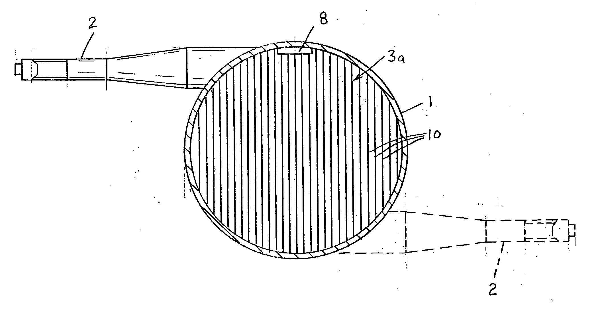
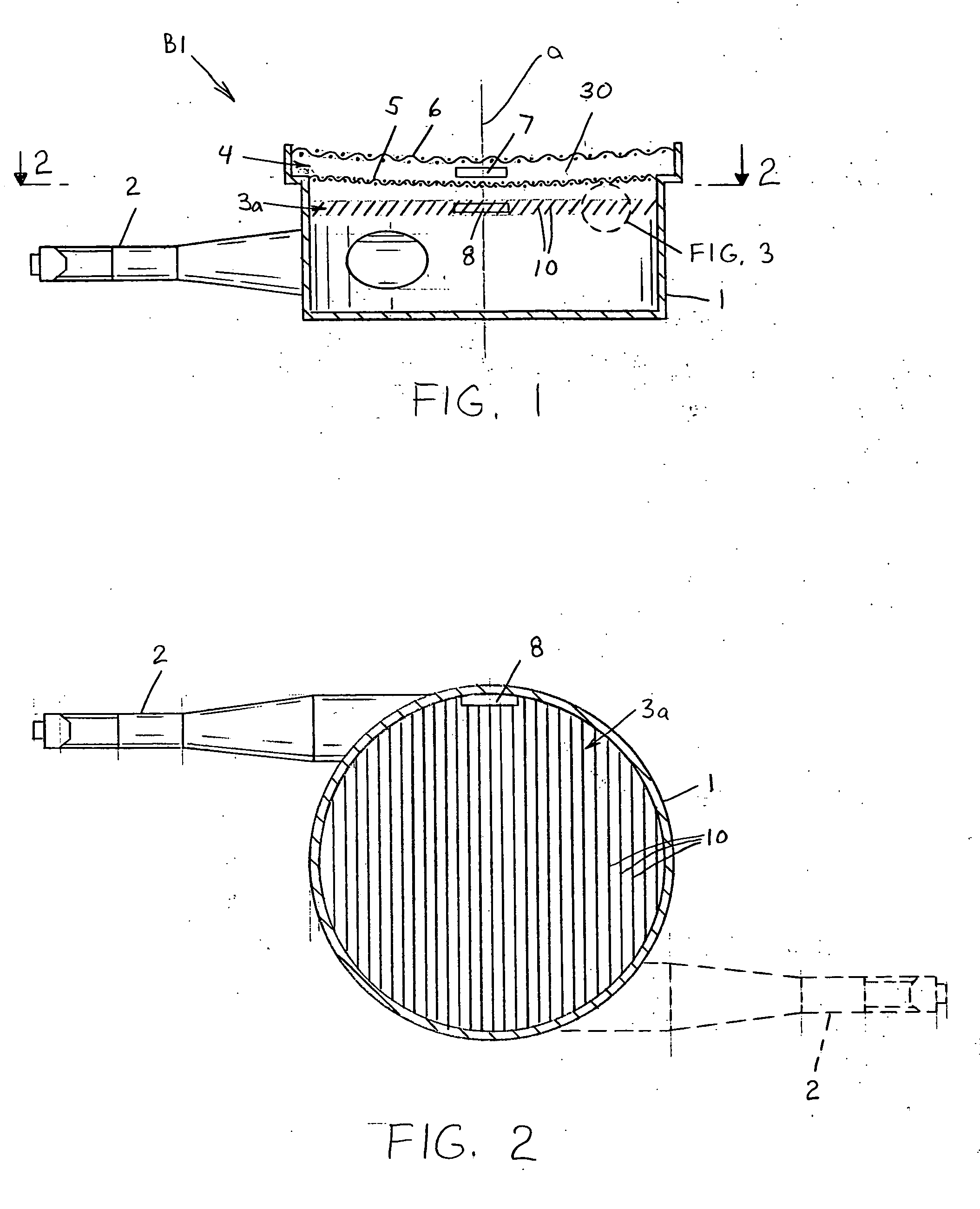
[0027] Referring now to FIGS. 1 and 2, FIG. 1 displays a radiant gas burner for gas fuel combustion, which comprises a cylindrical casing 1, an injection-type air-gas mixer 2, a gas dissector 3a, and a metallic-mesh emitter 4 having a lower mesh 5 and an tipper mesh 6 forming a convex-concave lens. The casing includes an aperture 7 located in between the lower mesh 5 and the upper mesh 6 of emitter 4. Gas dissector 3a can also include an aperture 8 adjoining casing 1 (refer to FIG. 2). Apertures 7 and 8 can be the same size and can be located so that the distance between their centers is minimal.

[0028] The radiant gas burner operates as described below. The gas entering mixer 2 injects some amount of air necessary for combustion and is mixed therewith. The injection-type gas mixer 2 can be fixed to cylindrical casing 1 so that air-gas mixture enters casing 1 tangentially at low velocity. The air-gas mixture flux can acquire rotary motion, thereby moving circularly inside casing 1 an...

second embodiment

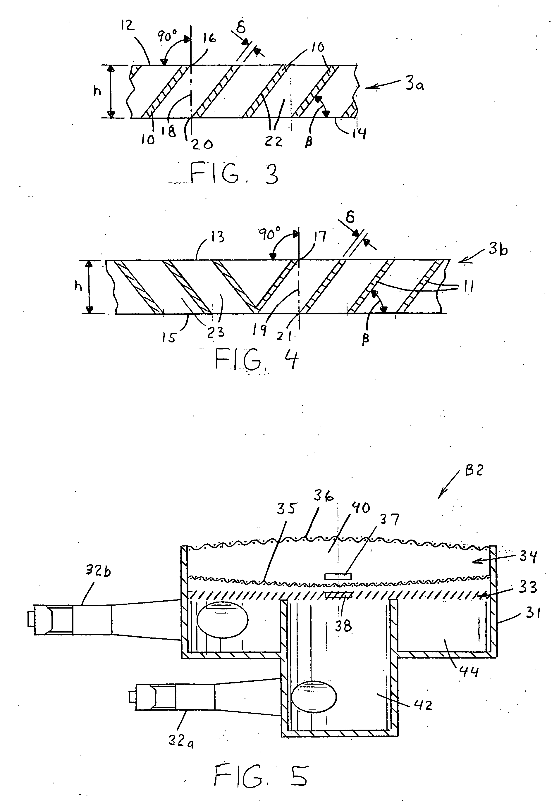
[0048]FIG. 5 shows a radiant gas burner B2 including casing 31, consisting of two parts or segments. The casing has central 42 and peripheral 44 parts with one air-gas mixer 32a, 32b attached to each of them respectively. The burner B2 also includes a gas dissector 33 and a metallic-mesh emitter 34 including a lower mesh 35 and an upper mesh 36 that form a biconvex lens having an inter mesh area 40 therebetween. A pair of apertures 37, 38 can be positioned in the inter-mesh area and the dissector 33, respectively.

[0049] In such burner design, the air-gas mixture can go to different parts of the casing both simultaneously and in turn. In other respects gas fuel combustion occurs as described for the burner design shown in FIG. 1.

[0050] In one preferred version of the burner, a metallic-mesh emitter was used with square openings of 0.5×0.5 mm for the lower mesh and 3×3 mm for the upper one. Referring to table 4, comparative experiments were made using a conventional gas-plasma burner...


PUM


Abstract

A radiant gas burner is provided having a casing adapted for connection with an air-gas mixing and supply system including a flux dissector and a mixer. The burner further includes a metallic mesh emitter inside the casing having lower and upper meshes. The lower mesh and the upper mesh each have porous openings. Each of the lower and upper meshes having a radius of curvature wherein the lower mesh is spaced apart from the upper mesh.

Description

FIELD OF INVENTION [0001] The invention relates to the field of engineering with respect to combustion of gaseous fuel and gas heaters / burners. More specifically, the present invention relates to radiant gas burners applied both in industrial and consumer applications. [0002] Infrared Radiation gas burners, alternatively referred to hereinafter as IR or radiant burners, allow the replacement of heat transfer by convection with more economical radiant or convective radiant means. IR gas burners enable increased heat transfer efficiency to an object being heated by using radiant heat exchange. Due to efficient radiant cooling of an emitting surface, the temperature in the combustion zone decreases which results in a much lower nitric oxide (NO) content in the combustion products. BACKGROUND OF THE INVENTION [0003] Ceramic matrices or sets of metallic meshes are used as radiating elements in radiant gas heaters. A radiant gas burner with a radiating element in the form of a two-layer c...

Claims


Application Information

Patent Timeline
IPC IPC(8): F23D14/62
CPCF23D14/145F23D2203/002F23D14/70F23D14/66Y02E20/34
Inventor KRAUKLIS, ANDREI V.LAPTSEVICH, PAWEL S.ZHDANOK, VATALI A.
Owner A V LUIKOV HEAT & MASS TRANSFER INST OF THE NAT ACADEMY OF SCI OF BELARUS
Why Eureka
Try Eureka