
Methods and apparatus for splitter modules and splitter module housings

a technology of splitter modules and splitter modules, applied in the field of optical fiber modules, can solve the problems of time-consuming assembly of art splitter modules, unsatisfactory cost-effectiveness, and conventional modules typically require a considerable amount of fiber space for fiber splicing

Inactive Publication Date: 2007-01-04
CORNING CABLE SYST LLC
View PDF12 Cites 210 Cited by
  • Summary
  • Abstract
  • Description
  • Claims
  • Application Information

AI Technical Summary

Problems solved by technology

In these conventional modules, the splitter input and outputs are spliced to connectorized cable assemblies and, for this reason, conventional modules typically require a considerable amount of fiber space for fiber splicing and routing.
These prior art splitter modules are time-consuming to assemble and thus are not desirable with respect to cost-effectiveness.

Method used


Image

  • Methods and apparatus for splitter modules and splitter module housings
  • Methods and apparatus for splitter modules and splitter module housings
  • Methods and apparatus for splitter modules and splitter module housings

Examples


Embodiment Construction

[0026] The present invention will now be described more fully hereinafter with reference to the accompanying drawings in which exemplary embodiments of the invention are shown. However, this invention may be embodied in many different forms and should not be construed as limited to the embodiments set forth herein. Like reference numbers refer to like elements throughout the various drawings.

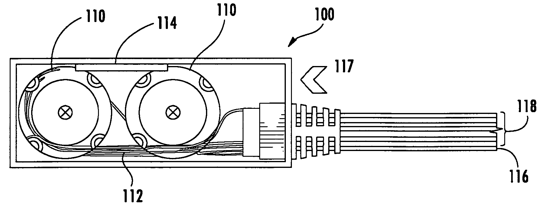
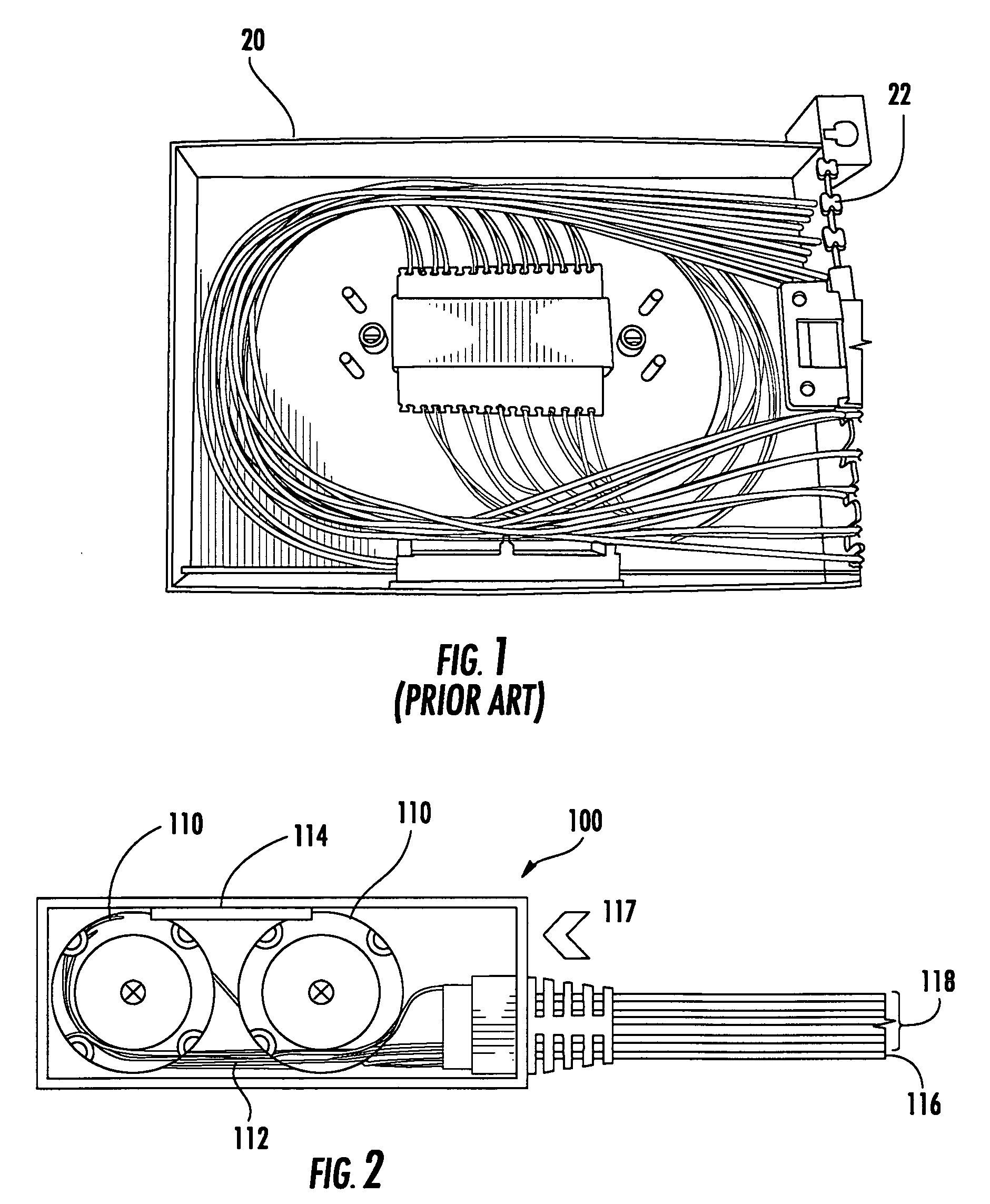
[0027]FIG. 1 illustrates a fiber layout inside a conventional splitter module 20. The known 1×N module design consists of a large metal housing designed to accommodate the 1×32 (or 1×16) optical splitter and the 33 (or 17) input / output connector assemblies. In module 20, the splitter input and outputs are spliced to connectorized cable assemblies and, for that reason, module 20 includes a relatively considerable amount of space for fiber splicing and routing. In addition, the fiber splicing and routing sometimes can be a cause of failures during assembly and / or qualification testing.

[0028] As ...


PUM


Abstract

Apparatus includes an optical splitter module including a housing, and an input optical fiber and an output optical fiber positioned with the housing, wherein at least one of the input and output optical fiber is partially potted.

Description

BACKGROUND OF THE INVENTION [0001] 1. Field of the Invention [0002] The present invention relates generally to optical fiber modules and, more particularly, to methods and apparatus for optical splitter modules. [0003] 2. Description of the Related Art [0004] Prior art 1×N optical splitter module designs typically consist of a large metal housing designed to accommodate a 1×32 (or 1×16) optical splitter and 33 (or 17) input / output connector assemblies. In these conventional modules, the splitter input and outputs are spliced to connectorized cable assemblies and, for this reason, conventional modules typically require a considerable amount of fiber space for fiber splicing and routing. These prior art splitter modules are time-consuming to assemble and thus are not desirable with respect to cost-effectiveness. Accordingly, there exists opportunities for improvement in optical splitter modules. BRIEF SUMMARY OF THE INVENTION [0005] In one aspect, apparatus includes an optical splitte...

Claims


Application Information

Patent Timeline
IPC IPC(8): G02B6/00
CPCG02B6/4478G02B6/4453
Inventor MAKRIDES-SARAVANOS, ELLILIU, ZIWEI
Owner CORNING CABLE SYST LLC
Features
  • Generate Ideas
  • Intellectual Property
  • Life Sciences
  • Materials
  • Tech Scout
  • Unparalleled Data Quality
  • Higher Quality Content
  • 60% Fewer Hallucinations
Learn More