Eureka AIR delivers breakthrough ideas for toughest innovation challenges, trusted by R&D personnel around the world.

Forward link based rescue channel method and apparatus for telecommunication systems

a forward link and rescue channel technology, applied in the direction of electrical equipment, network planning, selection arrangements, etc., can solve the problems of consumer switching service providers, critical or even fatal drop of emergency 911 connection, and cellular telephone users' distress

Inactive Publication Date: 2007-01-18
DENSO CORP
View PDF48 Cites 16 Cited by
  • Summary
  • Abstract
  • Description
  • Claims
  • Application Information

AI Technical Summary

Benefits of technology

[0100] In one embodiment of the present invention, only one sector will transmit on the ACC at any one time. Transmitting from only one sector provides an advantage of minimizing the capacity impact of a rescue, because in a forward rescue, the network knows its traffic and capacity and can coordinate within itself where and when to transmit the ACC. As illustrated in the example of FIG. 14, the sector will transmit on the ACC for only a set period of time 162 before it will stop and another sector will transmit, as the network cycles through its set of sectors.

Problems solved by technology

Dropped connections can range from being a nuisance to devastating for cellular telephone users.
For example, a dropped emergency 911 connection can be critical or even fatal.
Dropped connections can create consumer frustration significant enough to cause the consumer to change service providers.
However, because there are practical limitations the number of MSs that can be simultaneously paged using one paging channel, some BSs may employ multiple paging channels.
However, noise and interference in the field may require error correction to determine what was actually transmitted.
When the data is combined, the data from a strong channel may be weighted more heavily than data from a weak channel, which is likely to have more errors.
It should be noted, however, that the new active set may not always exactly comply with the MS's request, because the network may have BS resource considerations to deal with.
This is expected because poor coverage or weak signal environments generally exist near cell boundaries, in areas of pilot pollution, or areas significantly affected by cell breathing, all which are well known in the art.
Layer 2 Acknowledgment Failures and Forward Link Fade Failures may occur because of excessively high frame error rates or bursty error rates.
In a practical communications network, it is neither realistic nor desirable to target an error rate of zero percent (i.e., all frames received properly).
In this example, if the frame error rate rises above one percent, then the power control loop might increase the power of signals transmitted by the MS so that the frame error rate decreases to approximately one percent.
However, the BS may not necessarily change its transmitter power levels based on the feedback from the MS.
Despite the aforementioned power control loop, error rates may not be controllable to about one percent as a MS moves about in a cellular network and experiences variations in signal strength and signal quality due to physical impediments, interference from adjacent channels, and positions near the edges of sectors, and as the error rates rise to intolerable levels, dropped connections become a problem.
However, proposed rescue procedures based on restarting the connection utilize the access channel and require a lot of power because the MS is probing, which also introduces a lot of interference.
In addition, proposed reverse-based rescue procedures were activated only during a forward fade condition, and are deficient because the MS transmits before the BS, which is less efficient for reasons which will be explained hereinafter.

Method used


Image

  • Forward link based rescue channel method and apparatus for telecommunication systems
  • Forward link based rescue channel method and apparatus for telecommunication systems
  • Forward link based rescue channel method and apparatus for telecommunication systems

Examples


Embodiment Construction

.” The further implementation of embodiments of this invention with other messaging protocols and data structures and communication systems is straightforward to one skilled in the art.

BRIEF DESCRIPTION OF THE DRAWINGS

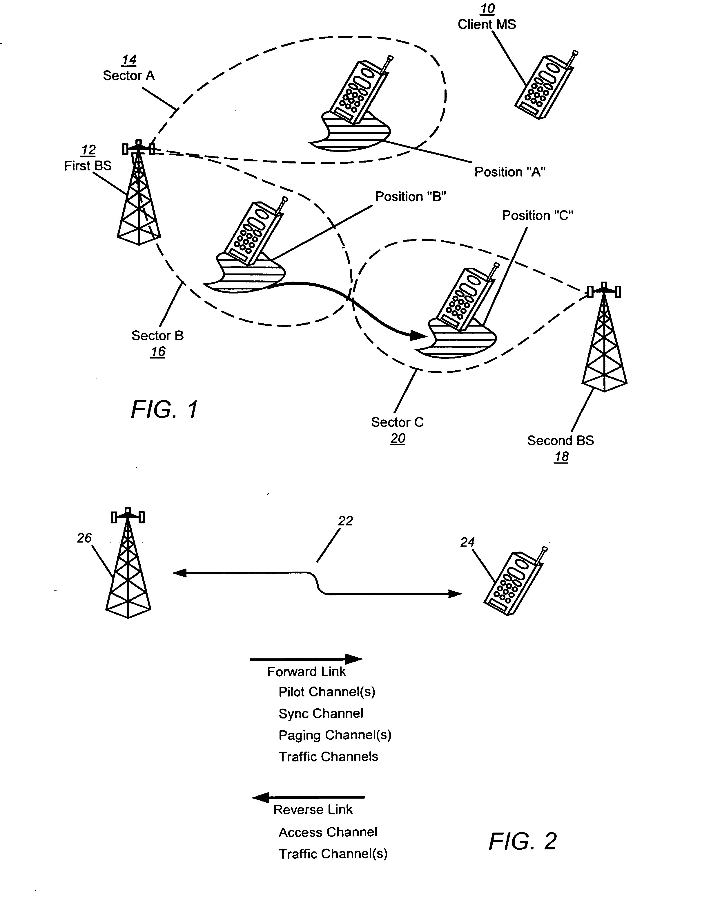
[0032]FIG. 1 illustrates a roving mobile station moving amongst different locations between sectors in a wireless communication system.

[0033]FIG. 2 illustrates an exemplary communication link between a mobile station and a base station in a wireless communication system.

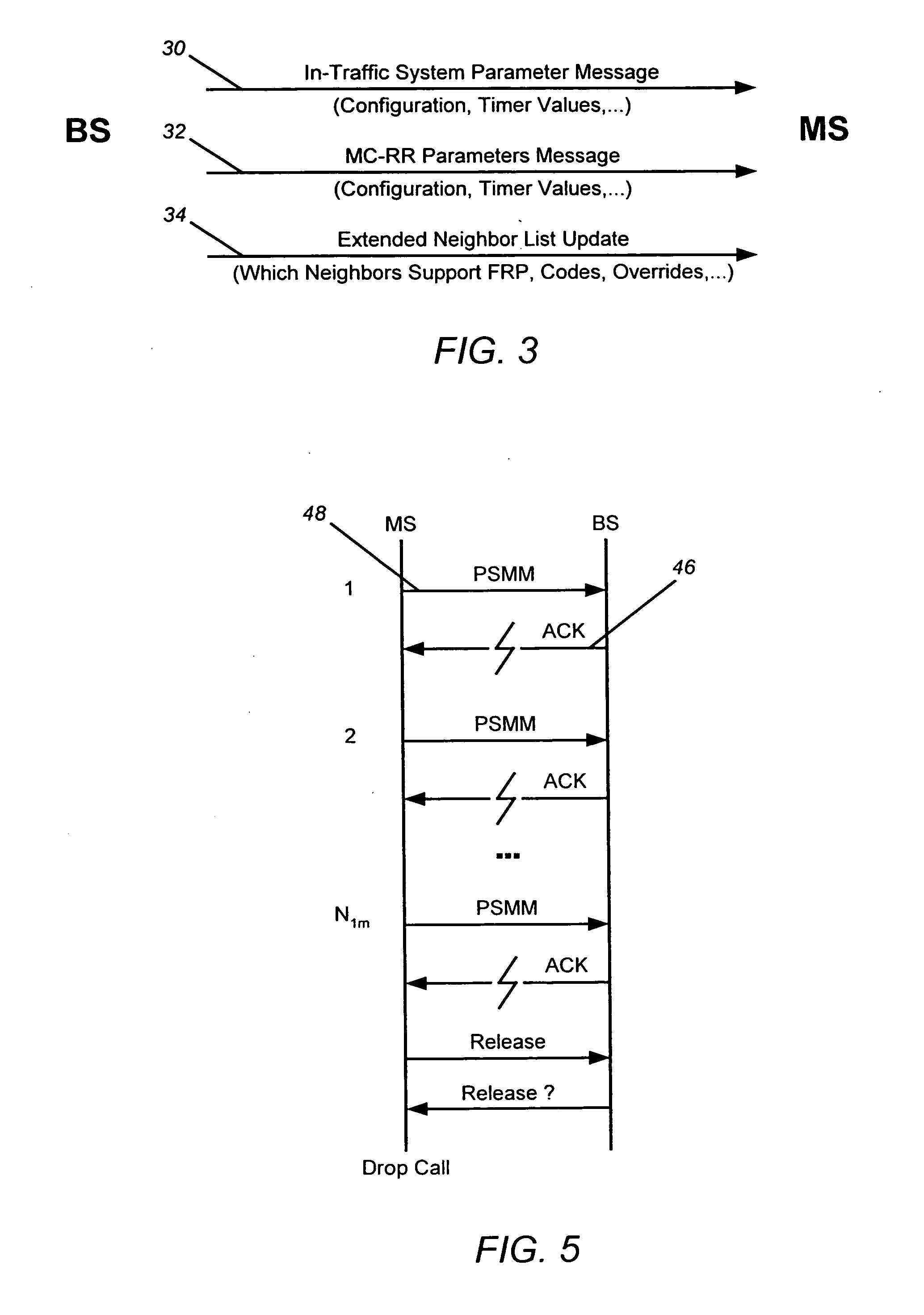
[0034]FIG. 3 illustrates overhead messages communicated from a base station to a mobile station in a wireless communication system.

[0035]FIG. 4 illustrates a wireless communication infrastructure in communication with a roving mobile station.

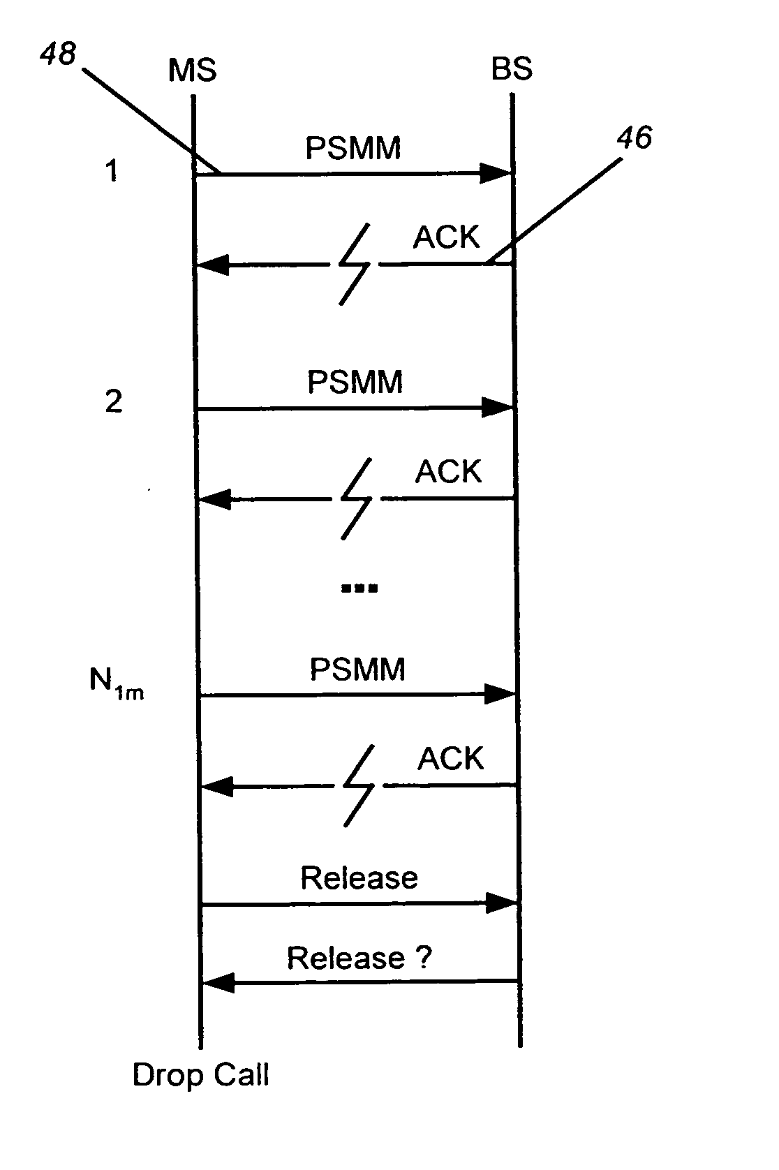
[0036]FIG. 5 is a message sequence between a mobile station and a base station resulting in a dropped connection due to Layer 2 Acknowledgement failure.

[0037]FIG. 6 is a timeline that is representative of a dropped connection resulting from fading of the forwa...


PUM


Abstract

A forward rescue procedure (FRP) for preventing loss of signal and dropped connections between a mobile station and the infrastructure in a wireless telecommunications network is disclosed. The FRP allows wireless systems to recover from forward link failures at the mobile station that would otherwise result in dropped connections. Examples of failure scenarios that can be overcome using the FRP include forward link Layer 2 acknowledgement failures and loss of forward link signal due to a fade that causes loss of signal for a period of time exceeding a threshold value. In response to a potential connection drop situation, a mobile station will autonomously add base station pilot channels to the active set of its rake receiver in order to rescue the connection in danger of dropping. Concurrently, the wireless network infrastructure will initiate transmission on alternative forward link channels that are likely to be monitored by the mobile station during an FRP. If the same channels are monitored by the MS and transmitted on by the infrastructure, the connection in danger of dropping can be rescued.

Description

CROSS-REFERENCE TO RELATED APPLICATIONS [0001] This application is a division of application Ser. No. 09 / 978,974 filed on Oct. 16, 2001, which claims the benefit under 35 USC 119(e) of U.S. provisional patent application Ser. No. 60 / 241,268 filed Oct. 17, 2000, and U.S. provisional patent application Ser. No. 60 / 248,900 filed Nov. 14, 2000, the contents of the prior applications which are incorporated herein by reference for all purposes.BACKGROUND OF THE INVENTION [0002] 1. Field of the Invention [0003] The present invention relates, generally, to communication network management and, in one embodiment, to methods and apparatus for preventing loss of signal and dropped connections between a mobile station, such as a cellular or PCS phone, and a wireless communication infrastructure (network). [0004] 2. Description of Related Art INTRODUCTION [0005] Rather than just providing a means for emergency communications, cellular telephones are rapidly becoming a primary form of communicati...

Claims


Application Information

Patent Timeline
Patent Type & Authority Applications(United States)
IPC IPC(8): H04Q7/20H04W16/06
CPCH04W16/06
Inventor HUNZINGER, JASON F.
Owner DENSO CORP
Why Eureka
Eureka Blog
Learn More