
Illuminated touch control interface

a touch control interface and illumination technology, applied in the field of touch sensor and touch control technology, can solve the problems of signal interference with the touch sensing system, difficulty and expense associated with illuminating the predefined touch area of the interface,

Inactive Publication Date: 2007-01-25
TYCO ELECTRONICS CANADA
View PDF15 Cites 33 Cited by
  • Summary
  • Abstract
  • Description
  • Claims
  • Application Information

AI Technical Summary

Benefits of technology

[0007] In another aspect, a touch control interface is provided including a panel having first and second surfaces, wherein the first surface defines a touch interface area having a touch sensitive element therein. The panel includes a cut-out extending entirely between the first and second surfaces, and the touch sensiti...

Problems solved by technology

Various types of technologies are available for use in touch control interfaces, including but not limited to touch sensitive elements such as, for example, capacitive sensors and infrared detectors, and switching elements (e.g., membrane switch assemblies) responsive to touch keypads However, at least one drawback with these known touch control interfaces is the difficulty and expense associated with illuminating the predefined touch area of the interface.
Additionally, problems exist with positioning lighting sources proximate to the touch sensors.
Specifically, the lighting sources may cause signal interference with the touch sensing system when the lighting sources are positioned too close to the touch sensors.
Thus, lighting known touch control interfaces is difficult and costly, or may be inadequate for the particular application.

Method used


Image

  • Illuminated touch control interface
  • Illuminated touch control interface
  • Illuminated touch control interface

Examples


Embodiment Construction

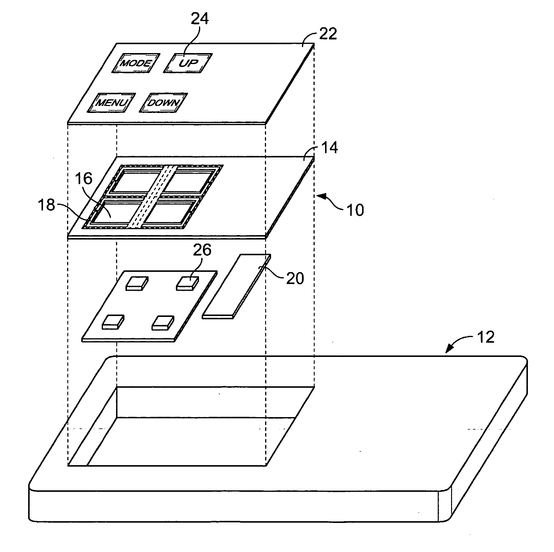
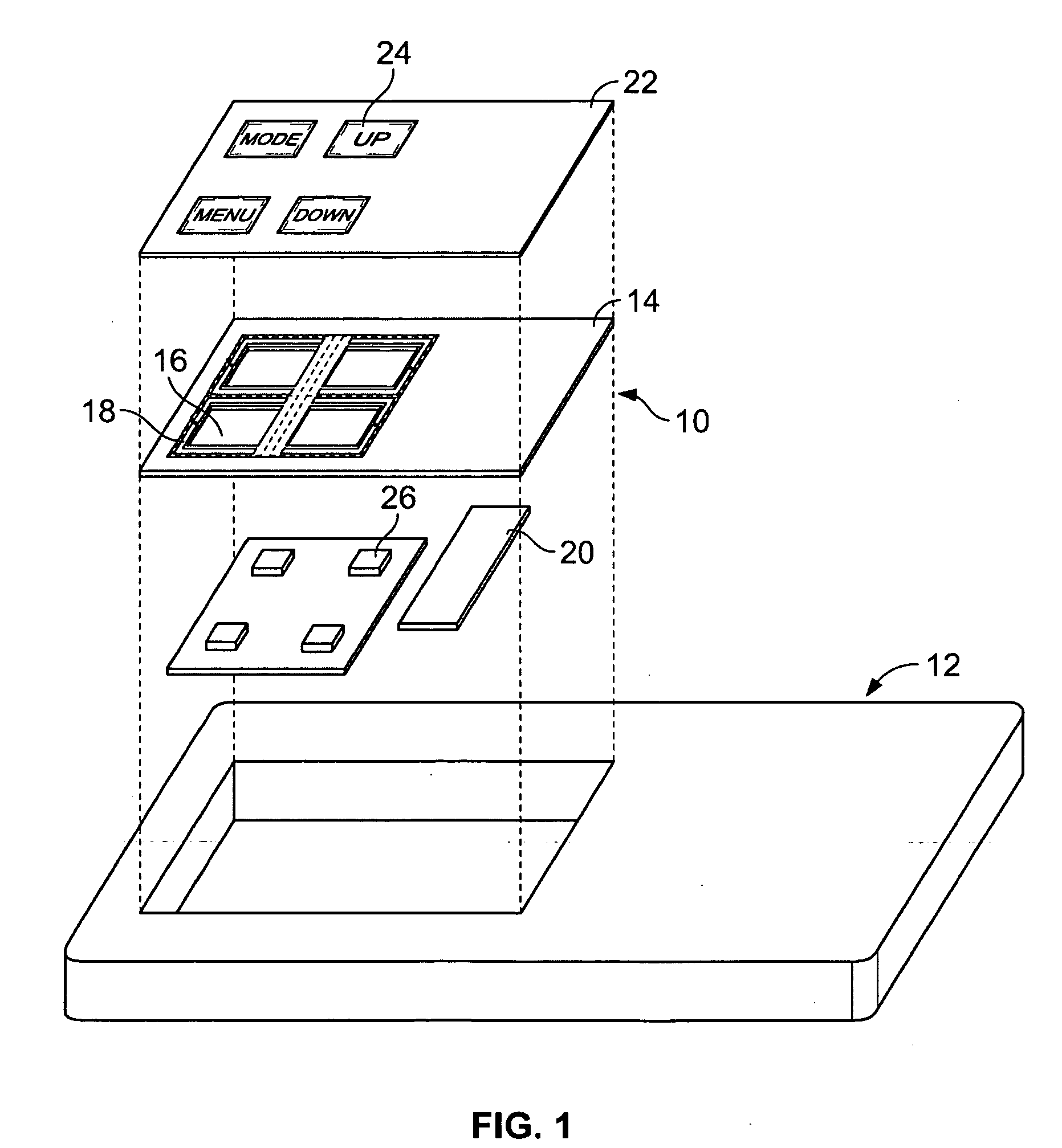
[0014]FIG. 1 is an exploded perspective view of a touch control interface 10 for an electronic device or product 12. The device 12 may be applicable to, but is not limited to applications such as appliances, industrial processes or equipment, automotive equipment, kiosks, point of sale terminals, medical equipment, mobile communications, portable electronic entertainment, hand held instrumentation or other electronic applications. More specifically, the touch control interface 10 may be utilized within electronic devices 12 utilizing a human interface such as, for example, touch control technology, padless touch sensor technology, capacitive touch sensing systems, or like systems that use signal generation and detection, as those in the art would appreciate.

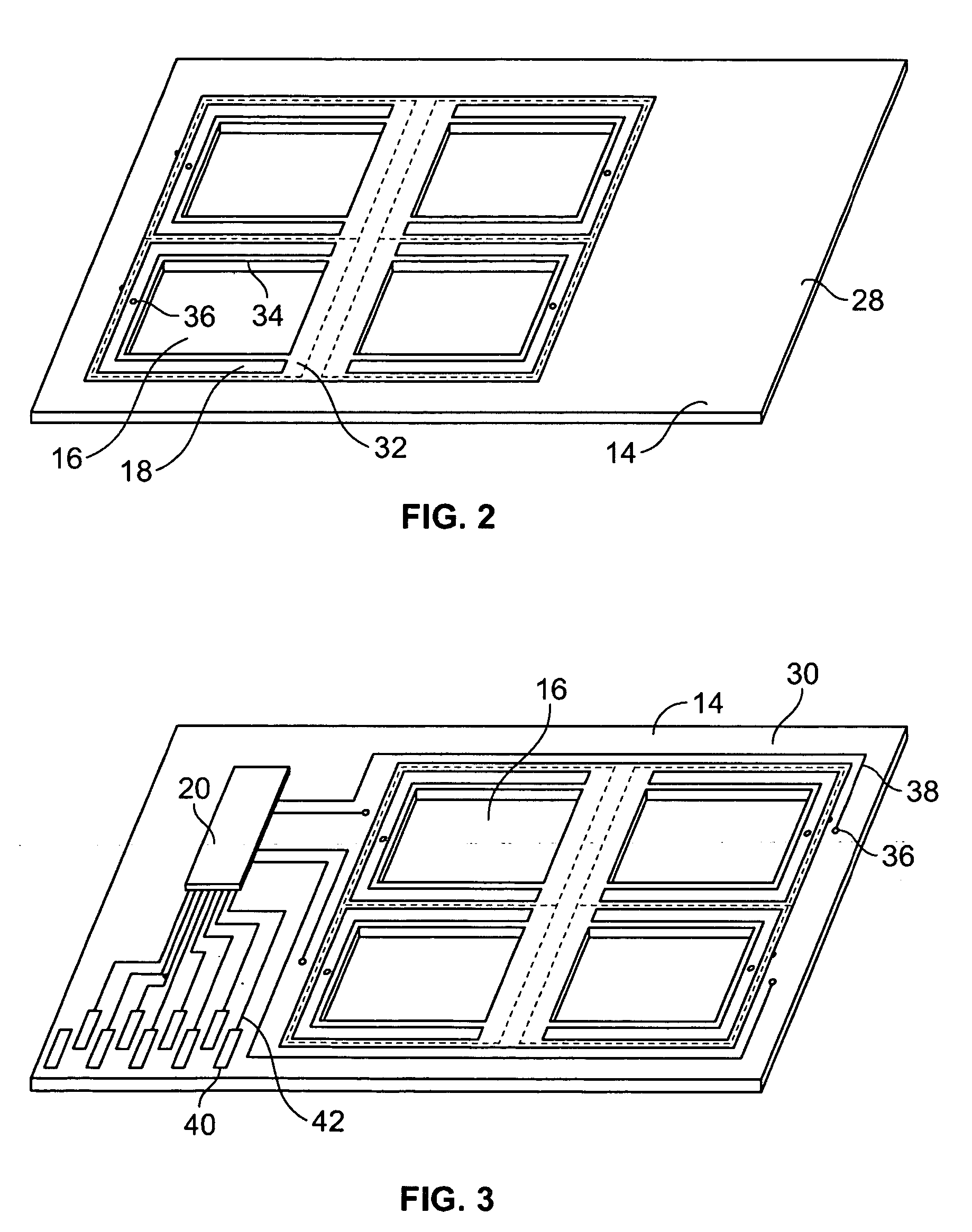
[0015] The touch control interface 10 includes an interface panel or circuit board 14 having a plurality of openings or cut-outs 16 which are surrounded by touch sensitive elements 18, also referred to hereinafter as touch plate...


PUM


Abstract

A touch control interface includes a panel having first and second surfaces. The first surface defines a touch interface area. The panel includes an opening extending entirely between the first and second surfaces, and the panel includes at least one touch sensitive element positioned within the touch interface area. An illumination source is positioned proximate the opening for transmitting light through said opening.

Description

BACKGROUND OF THE INVENTION [0001] This invention relates generally to touch sensor and touch control technologies, and more particularly, to illuminated keyboard assemblies applicable to touch control technologies. [0002] Due to their convenience and reliability, touch sensitive control interfaces are increasingly being used in lieu of mechanical switches for various products and devices. Conventional touch control interfaces, or touch sensing systems are utilized in a variety of electronic applications such as, for example, appliances, industrial processes or equipment, automotive equipment, kiosks, point of sale terminals, medical equipment, mobile communications, portable electronic entertainment, hand held instrumentation or other electronic applications. The associated device may be finger operated by pressing predefined areas of the interface, and the device typically includes a controller coupled to the interface to operate mechanical and electrical elements of the device in...

Claims


Application Information

Patent Timeline
IPC IPC(8): G09G5/00
CPCH01H13/702H03K2217/960755H01H2209/082H01H2209/084H01H2219/014H01H2219/018H01H2223/014H01H2239/004H01H2239/006H01H2239/01H01H2239/022H03K17/96H03K17/962H03K2217/96042H01H2207/01
Inventor PAUN, TRAIAN RADUATANASSOV, FILIP
Owner TYCO ELECTRONICS CANADA
Learn More