Antenna device and radio apparatus capable of multiband operation

a radio communication apparatus and antenna device technology, applied in the direction of antenna details, elongated active element feed, antennas, etc., can solve the problems of monopolizing antennas, and not being suitable for radio applications

Active Publication Date: 2007-02-15
TOSHIBA CLIENT SOLUTIONS CO LTD
View PDF4 Cites 119 Cited by
  • Summary
  • Abstract
  • Description
  • Claims
  • Application Information

AI Technical Summary

Benefits of technology

[0012] Accordingly, an advantage of the present invention is that a resonant frequency of an antenna device may be significantly changed while causing little mismatch of the antenna's input impedance.
[0013] To achieve the above advantage, one aspect of the present invention is to provide an antenna device and a radio apparatus capable of multiband operation. The antenna device is configured to be coupled to a feeding point of the radio apparatus. The antenna device has a first antenna element and a second antenna element. The first antenna element is configured to be an unbalanced-fed antenna fed at the feeding point to resonate at a first frequency. The second antenna element is configured to be a monopole antenna having an open end and to be fed at the feeding point. The first antenna element and the second antenna element have a common portion from the feeding point to a branching point. The second antenna element is configured to be ungrounded in a first state to resonate at a second frequency lower than the first frequency and to be grounded in a second state at a switch point between the branching point and the open end.

Problems solved by technology

Hence, there is a problem that the above antennas may not be suitable for an application that needs a significant change of the resonant frequency, e.g., WLANs.
The T-type monopole antenna, however, may not be suitable for a radio apparatus a feeder system of which is designed to match the input impedance of the antenna at a series resonant frequency of the antenna, as the increase of the input impedance in the parallel resonant mode is likely to cause a mismatch.

Method used


Image

  • Antenna device and radio apparatus capable of multiband operation
  • Antenna device and radio apparatus capable of multiband operation
  • Antenna device and radio apparatus capable of multiband operation

Examples


first embodiment

1. First Embodiment of the Present Invention

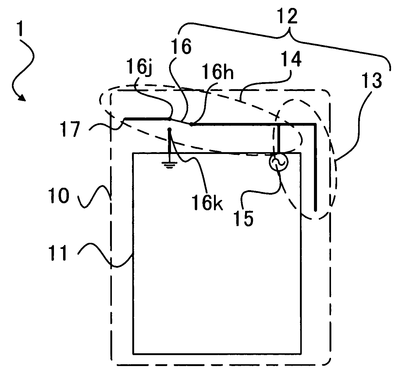
[0038] A first embodiment of the present invention will be described with reference to FIGS. 1 to 6. FIG. 1 shows a configuration of a radio apparatus 1, including an antenna device, of the first embodiment. The radio apparatus 1 of the first embodiment has a case 10 indicated by a dot-and-dash line. The radio apparatus 1 has a printed board 11 and an antenna device 12 contained in the case 10.

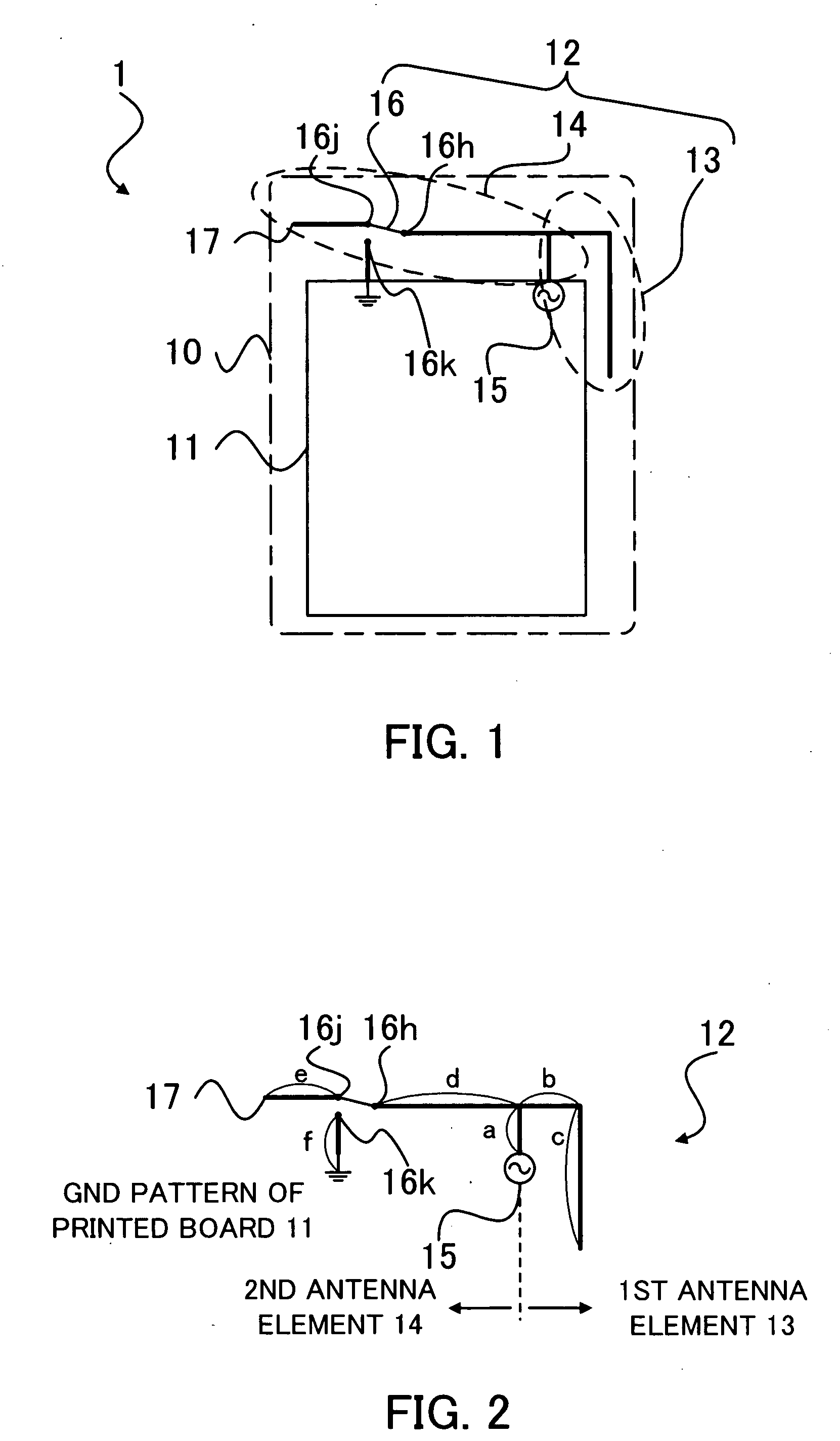
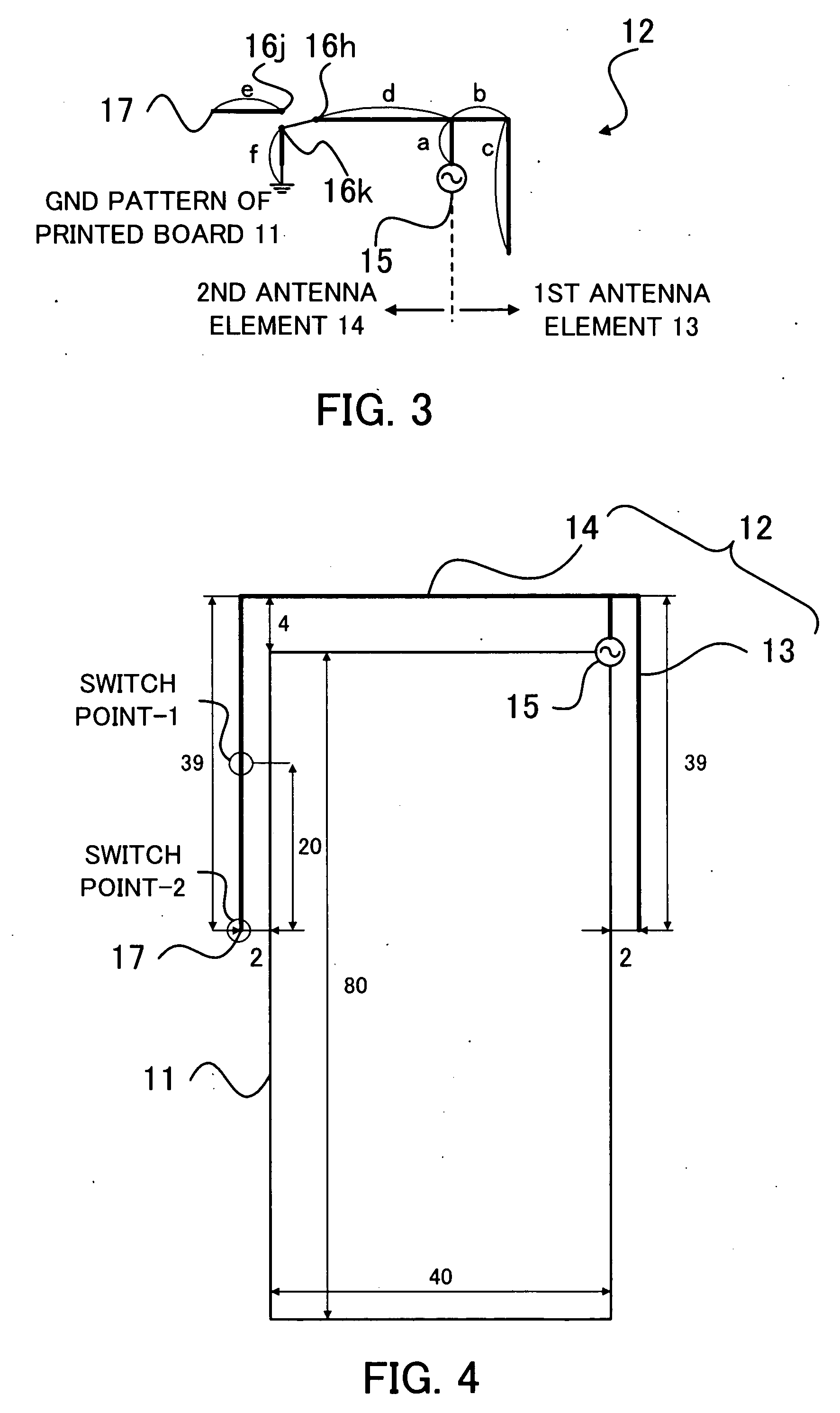
[0039] The antenna device 12 includes a first antenna element 13 indicated as encircled by a dashed ellipse on a right hand side of FIG. 1, and a second antenna element 14 encircled by another dashed ellipse on a left hand side of FIG. 1. The first antenna element 13 and the second antenna element 14 are fed in common at a feeding point 15 located on the printed board 11. The first antenna element 13 is located near an end of the printed board 11, and so is the second antenna element 14.

[0040] The antenna device 12 includes a switch element 16 loca...

second embodiment

2. Second Embodiment of the Present Invention

[0061] A second embodiment of the present invention will be described with reference to FIGS. 7 to 12. FIG. 7 shows a configuration of a radio apparatus 2, including an antenna device, of the second embodiment. The radio apparatus 2 of the second embodiment has a case 20 indicated by a dot-and-dash line. The radio apparatus 2 has a printed board 21 and an antenna device 22 contained in the case 20.

[0062] The antenna device 22 includes a first antenna element 23 indicated as encircled by a dashed ellipse on a right hand side of FIG. 7, and a second antenna element 24 on a left hand side of FIG. 7. The first antenna element 23 and the second antenna element 24 are fed in common at a feeding point 25 located on the printed board 21. The first antenna element 23 is located near an end of the printed board 21, and so is the second antenna element 24.

[0063] The antenna device 22 has a switch point 26 which is a middle location of the second a...

third embodiment

3. Third Embodiment of the Present Invention

[0081] A third embodiment of the present invention will be described with reference to FIGS. 13 to 16. FIGS. 13 and 14 show configurations of antenna devices 12a and 12b, respectively, of the third embodiment. FIGS. 15 and 16 show configurations of antenna devices 22a and 22b, respectively, of the third embodiment.

[0082] The antenna device 12a shown in FIG. 13 is configured in such a way that the antenna device 12 of the first embodiment shown in FIG. 2 is loaded with a reactance element 18 between the switch point of the antenna device 12 (or the terminal 16j of the switch element 16) and the open end 17. Each of remaining portions of the antenna device 12a is a same as the corresponding one shown in FIG. 2 given the same reference numeral, and its explanation is omitted.

[0083] The antenna device 12b shown in FIG. 14 is configured in such a way that the antenna device 12 of the first embodiment shown in FIG. 2 is loaded with a reactance...


PUM


Abstract

An antenna device and a radio apparatus are provided. The antenna device is configured to be coupled to a feeding point of the radio apparatus. The antenna device has a first antenna element and a second antenna element. The first antenna element is configured to be an unbalanced-fed antenna fed at the feeding point to resonate at a first frequency. The second antenna element is configured to be a monopole antenna having an open end and to be fed at the feeding point. The first antenna element and the second antenna element have a common portion from the feeding point to a branching point. The second antenna element is configured to be ungrounded in a first state to resonate at a second frequency lower than the first frequency and to be grounded in a second state at a switch point between the branching point and the open end.

Description

CROSS REFERENCE TO RELATED APPLICATIONS [0001] This application is based upon and claims the benefit of priority from the prior Japanese Patent Application No. 2005-230298 filed on Aug. 9, 2006; the entire contents of which are incorporated herein by reference. FIELD OF THE INVENTION [0002] The present invention relates to an antenna device and a radio communication apparatus capable of multiband operation, and in particular to those adapted for mobile use. DESCRIPTION OF THE BACKGROUND [0003] As radio apparatus like mobile phones, etc. come into wide use and have a wider range of application, antennas having a broader frequency range are required more than ever for radio apparatus. For instance, it is thought that an ultra-high frequency (UHF) band as broad as a couple of hundred megahertz (MHz) is required for receiving terrestrial digital television broadcast. In order that a radio apparatus using a single antenna for downsizing is adapted for two or more standards of wireless lo...

Claims


Application Information

Patent Timeline
Patent Type & Authority Applications(United States)
IPC IPC(8): H01Q1/24
CPCH01Q1/243H01Q5/371H01Q9/42H01Q9/145
Inventor OHBA, ISAO
Owner TOSHIBA CLIENT SOLUTIONS CO LTD
Why Eureka
Try Eureka