Helmet that reports impact information, and associated methods

a technology of impact information and helmet, applied in the field of monitoring and quantifying sport movement, can solve the problems of cyclical periods of relatively small vibration, she might remain motionless for thirty seconds or more, etc., and achieve the effect of reliable determination of speed

Inactive Publication Date: 2007-03-15
PHATRAT TECH
View PDF51 Cites 48 Cited by
  • Summary
  • Abstract
  • Description
  • Claims
  • Application Information

AI Technical Summary

Benefits of technology

[0114] In still another aspect, when using a GPS receiver, individual ski maps for each trail are downloaded into memory so that the skier may see where they are on the display. Also, 3D topographical information is also preferably downloaded so that features can be attached to these maps and to aid in performance data determination. By knowing the height in 3D space of the receiver, and with the stored height of the slope in memory, the distance off the ground is determined. Loft time is also thus determined in addition to vertical drop. Loft detection with a GPS system may thus return the value of drop distance.
[0115] In another aspect, speed is determined by use of neural network synthesis. A neural network extracts speed information from a sensor such as a microphone or an accelerometer. This is accomplished, for example, by recording microphone data on a ski or snowboard along with a true speed sensor, such as a Doppler microwave sensor. Two data sets are thus generated: the first data set contains data acquired from the microphone that will be used in the final system; and the second data set corresponds to the true device that is used as a reliable speed detector. These two data sets are fed into a neural network, and the output of the neural filter is then compared with known good speed data. The various weights of the neural network are adjusted until a match is determined. At this point, the neural network is used to process the first data set to reliably determine speed. In the event that a match is not found, a more complex but powerful network is developed. The first data set is then fed into the new net and a match is developed by adjusting the weights of the nodes. This process is repeated constantly until a match is determined. Each failure results in a larger neural network but increases the probability that the next filter will achieve a match.

Problems solved by technology

However, when such a user stands in line for the chair-lift, she might remain motionless for thirty seconds or more.
Similarly, when a user walks slowly, there are cyclical periods of relatively small vibration (e.g., when the user lifts his foot off the ground).

Method used


Image

  • Helmet that reports impact information, and associated methods
  • Helmet that reports impact information, and associated methods
  • Helmet that reports impact information, and associated methods

Examples


Embodiment Construction

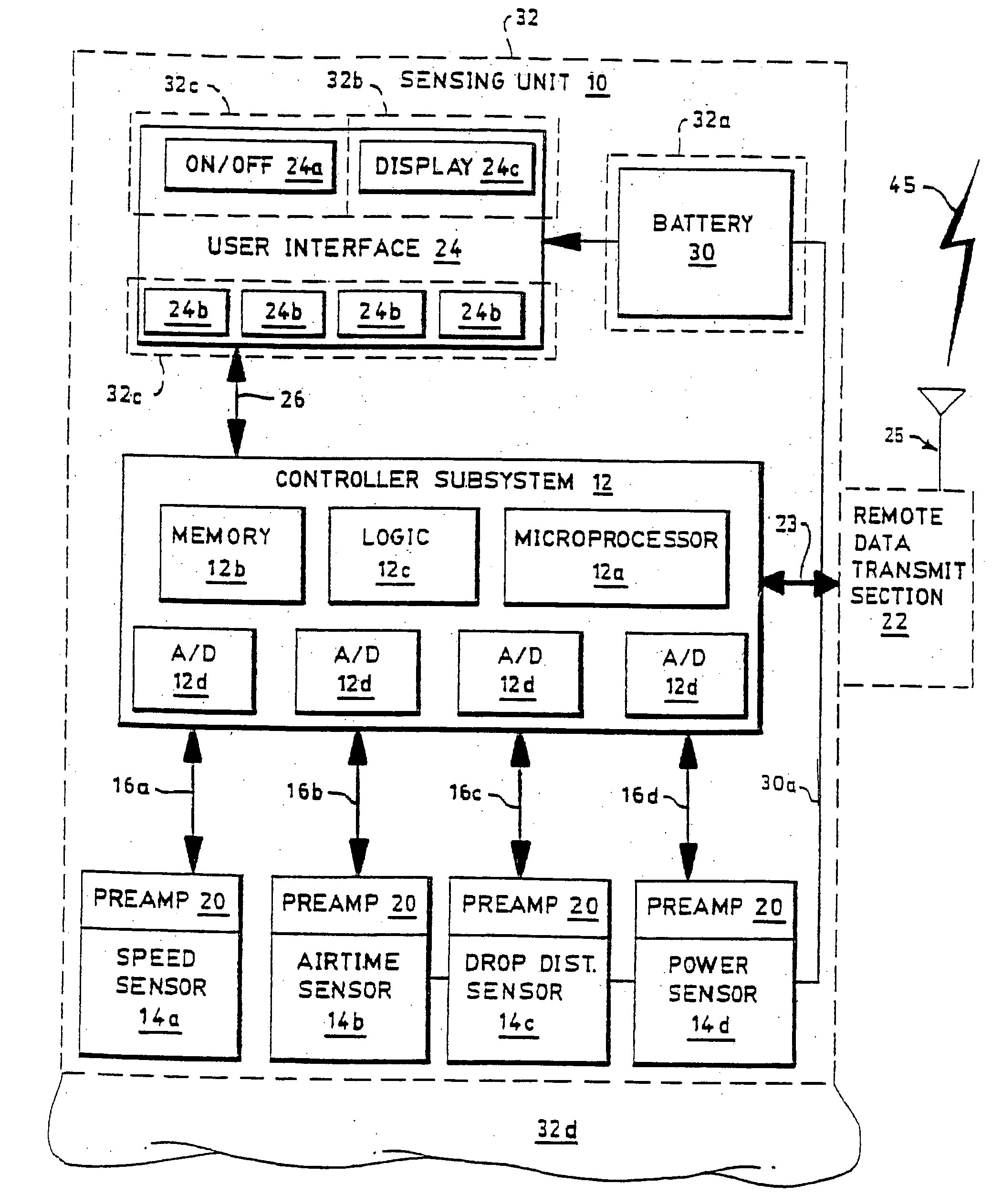
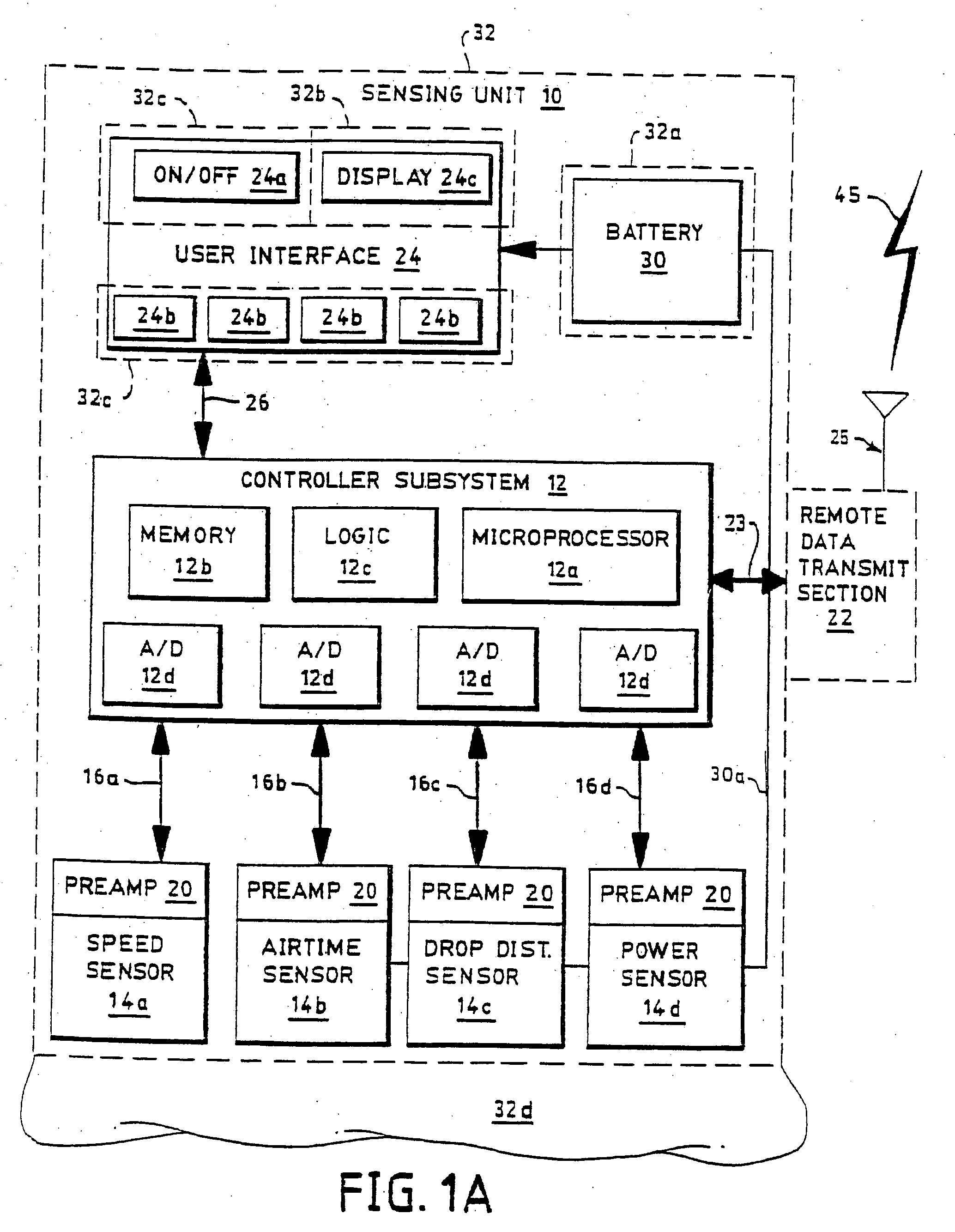
[0172]FIG. 1A illustrates a sensing unit 10 constructed according to the invention. A controller subsystem 12 controls the unit 10 and is connected to one or more sensors 14a-14d. Typically, the subsystem 12 receives data from the sensors 14a-d through data line 16a-d; though certain sensors 14 require or permit control signals, so data lines 16a-d are preferably bi-directional. It is not necessary that the unit 10 incorporate all sensors 14a-14d and only one of the sensors 14a, 14b, 14c or 14d is required so as to provide performance data. In one preferred embodiment, however, the unit 10 includes all four sensors 14a-14d. In another preferred embodiment, only the airtime sensor 14b is included within the unit 10.

[0173] The sensors 14a-14d take a variety of forms, as discussed herein. Generally, the speed sensor 14a provides data indicative of speed to the controller subsystem 12 along data line 16a. One exemplary speed sensor 14a utilizes a microwave Doppler module such as made b...


PUM


Abstract

A system determines impact of a helmet. The helmet includes at least one accelerometer and a processor. The accelerometer detects acceleration of the helmet. The processor is configured to process the signals from the accelerometer to determine impact of the helmet.

Description

RELATED APPLICATIONS [0001] This application is a divisional application of U.S. application Ser. No. 11 / 221,029, filed Sep. 5, 2005, which is a continuation of U.S. patent application Ser. No. 10 / 921,743, filed Aug. 19, 2004, which is a divisional of U.S. patent application Ser. No. 10 / 283,642, (filed Oct. 30, 2002 and now U.S. Pat. No. 6,959,259), which is a continuation of U.S. patent application Ser. No. 09 / 089,232 (filed Jun. 2, 1998 and now U.S. Pat. No. 6,539,336), which (a) claims priority to U.S. Provisional Application No. 60 / 077,251, filed on Mar. 9, 1998, and (b) is a continuation-in-part of U.S. application Ser. No. 08 / 867,083 (filed Jun. 2, 1997 and now U.S. Pat. No. 6,266,623), which is a continuation-in-part of U.S. patent application Ser. No. 08 / 344,485 (filed Nov. 21, 1994 and now U.S. Pat. No. 5,636,146). The '232 application is also a continuation-in-part of the '758 application. This application is also a continuation of U.S. application Ser. No. 10 / 842,947 (fil...

Claims


Application Information

Patent Timeline
Patent Type & Authority Applications(United States)
IPC IPC(8): G06F15/00A63B69/18A63B71/06G01P3/50G01S11/14G01S15/60G04F8/08
CPCA63B2220/74A42B3/046G01P3/50G01P15/00G01P15/0891G01S11/14G01S15/60G04F8/08A61B5/11A61B2562/0219A63B69/18A63B71/0605A63B71/10A63B2069/185A63B2220/40A63B2220/62G01L1/00A61B5/6895A61B5/6804A61B5/681G01C9/00A63C2203/18
Inventor VOCK, CURTIS A.DARCY, DENNISFLENTOV, PETER
Owner PHATRAT TECH
Why Eureka
Try Eureka