Gas fired cooktop and method of assembling

Inactive Publication Date: 2007-03-29
GENERAL ELECTRIC CO
View PDF24 Cites 10 Cited by
  • Summary
  • Abstract
  • Description
  • Claims
  • Application Information

AI Technical Summary

Problems solved by technology

Accordingly, it may not be possible to use all of the existing burners for cooking with utensils while using a griddle.
Alternatively, the addition of a griddle burner on some known cooktops will narrow the space

Method used


Image

  • Gas fired cooktop and method of assembling
  • Gas fired cooktop and method of assembling
  • Gas fired cooktop and method of assembling

Examples


Embodiment Construction

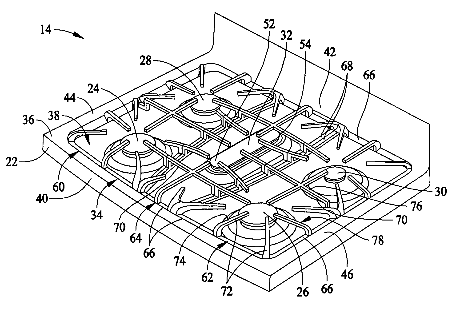
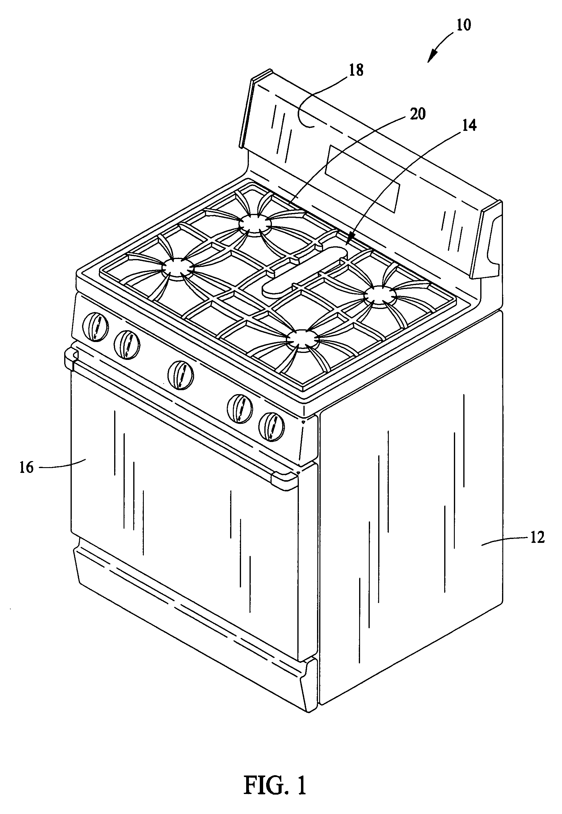
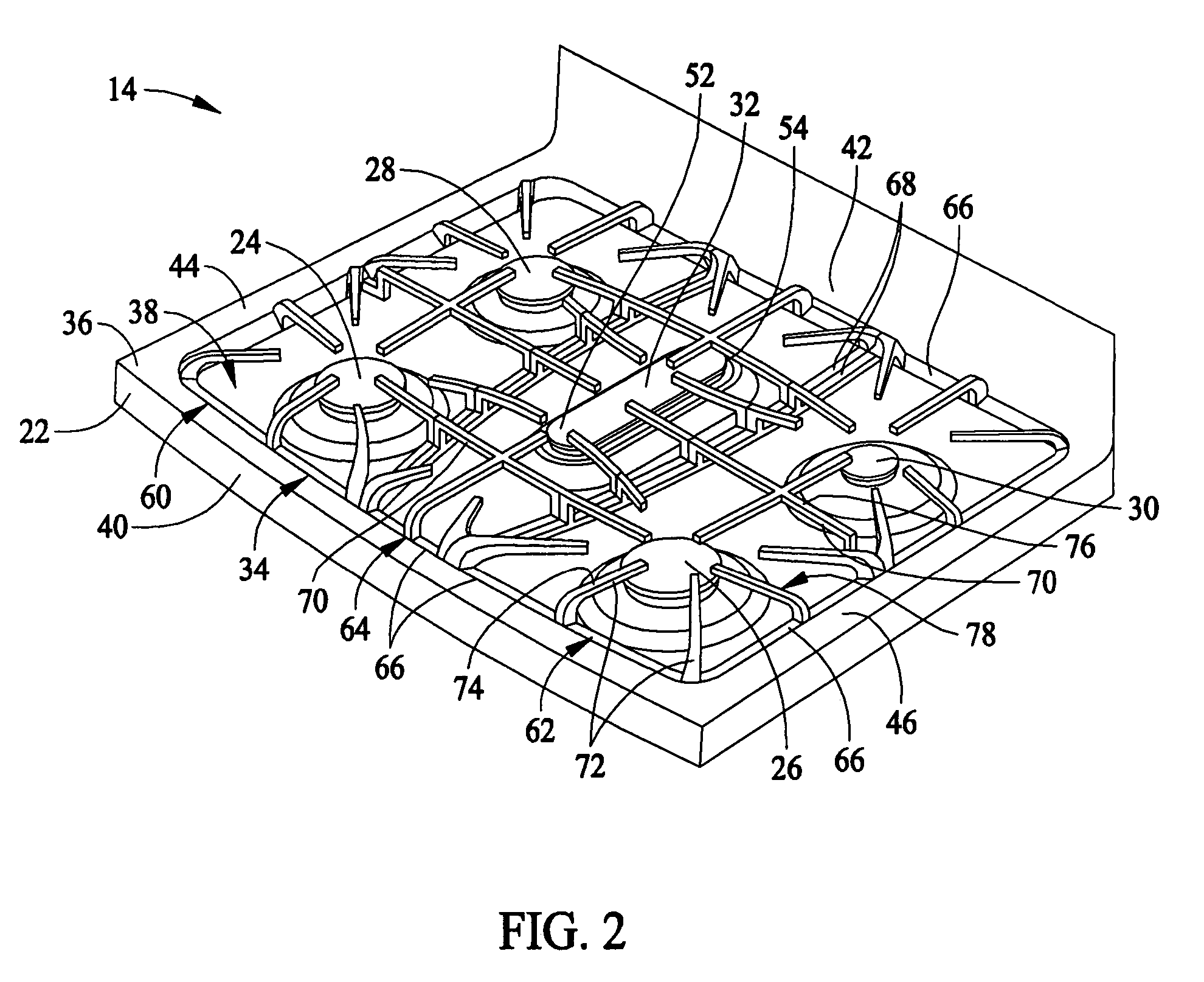
[0011]FIG. 1 illustrates a gas cooking appliance in the form of a free standing gas range 10 including an outer body or cabinet 12 that incorporates a generally rectangular cooktop 14. An oven, not shown, is positioned below cooktop 14 and has a front-opening access door 16. A range backsplash 18 extends upward of a rear edge 20 of cooktop 14 and includes, for example, a control display and control selectors for user manipulation to select operative oven features, cooking timers, time and temperature displays, etc. It is contemplated that the present invention is applicable, not only to cooktops which form the upper portion of a range, such as range 10, but to other forms of cooktops as well, such as, but not limited to, built-in counter units that are mounted to kitchen counters. Therefore, gas range 10 is provided by way of illustration rather than limitation, and accordingly there is no intention to limit application of the present invention to any particular appliance or cooktop...


PUM


Abstract

A gas burner assembly for a gas fired cooktop includes first, second, third, and fourth gas burners arranged such that the first and second burners are spaced with respect to each other at a first distance and the third and fourth burners are spaced with respect to each other at a second distance longer than the first distance. Each of the first and second burners have a power output greater than that of each of the third and fourth burners. A fifth gas burner is positioned between the first and second burners and between the third and fourth burners.

Description

BACKGROUND OF THE INVENTION [0001] This invention relates generally to gas cooking appliances, and, more specifically, to apparatus and methods for gas fired cooktops. [0002] Gas fired cooktops typically include a top surface having one or more openings with a gas burner set in each opening. In addition, a number of raised cooking grates rest on the cooktop, generally above and surrounding the burners to provide a cooking surface spaced from the burner. At least some known cooktops include four burners arranged on the top surface in a compact pattern. Cooking implements such as pots and pans are placed on the stove grates above the burners. [0003] Some gas fired cooktops also include a griddle component that is configured to either replace a set of burners or be positioned between existing burners. Accordingly, it may not be possible to use all of the existing burners for cooking with utensils while using a griddle. Alternatively, the addition of a griddle burner on some known cookt...

Claims


Application Information

Patent Timeline
IPC IPC(8): F24C3/00
CPCF24C3/027F24C15/10F24C3/08
Inventor CADIMA, PAUL BRYAN
Owner GENERAL ELECTRIC CO
Why Eureka
Try Eureka