Direct-current motor

Active Publication Date: 2007-03-29
DENSO CORP
View PDF10 Cites 6 Cited by
  • Summary
  • Abstract
  • Description
  • Claims
  • Application Information

AI Technical Summary

Benefits of technology

[0005] It is an object of the present invention to provide a dire

Problems solved by technology

However, it would be insufficient just to increase the number of magnetic

Method used


Image

  • Direct-current motor
  • Direct-current motor
  • Direct-current motor

Examples


Embodiment Construction

[0019] One embodiment of the present invention will now be described with reference to FIGS. 1 to 5.

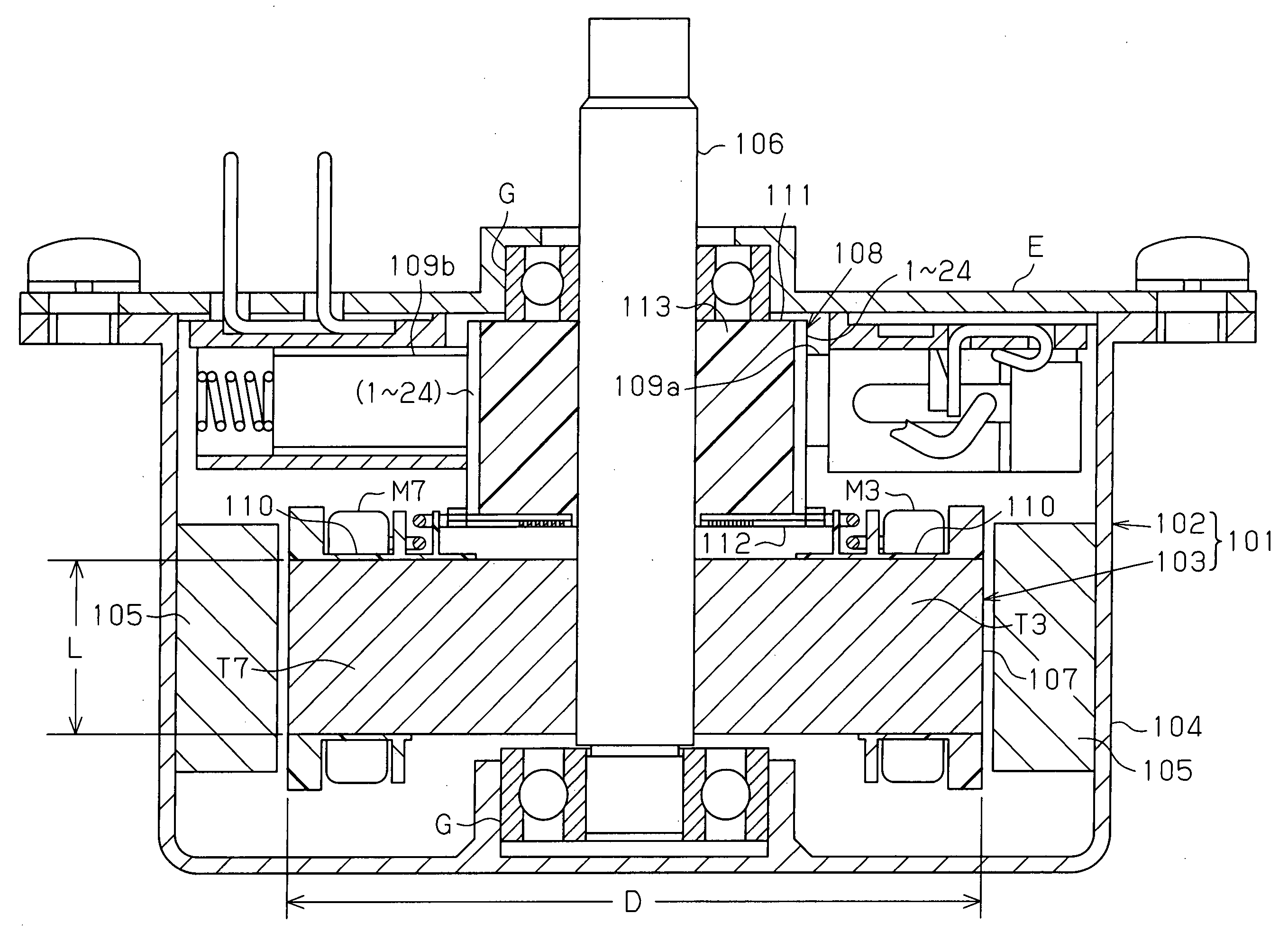
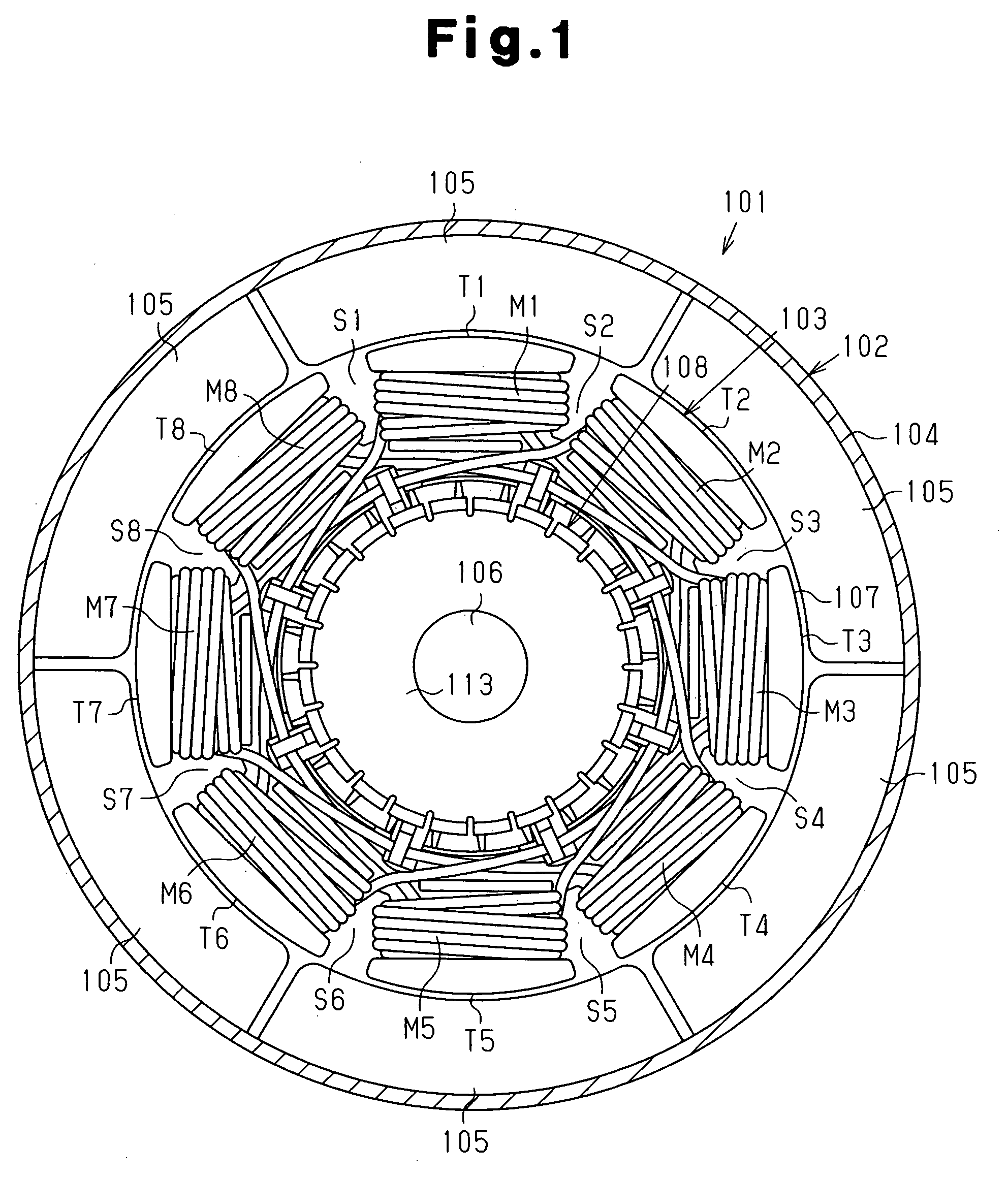
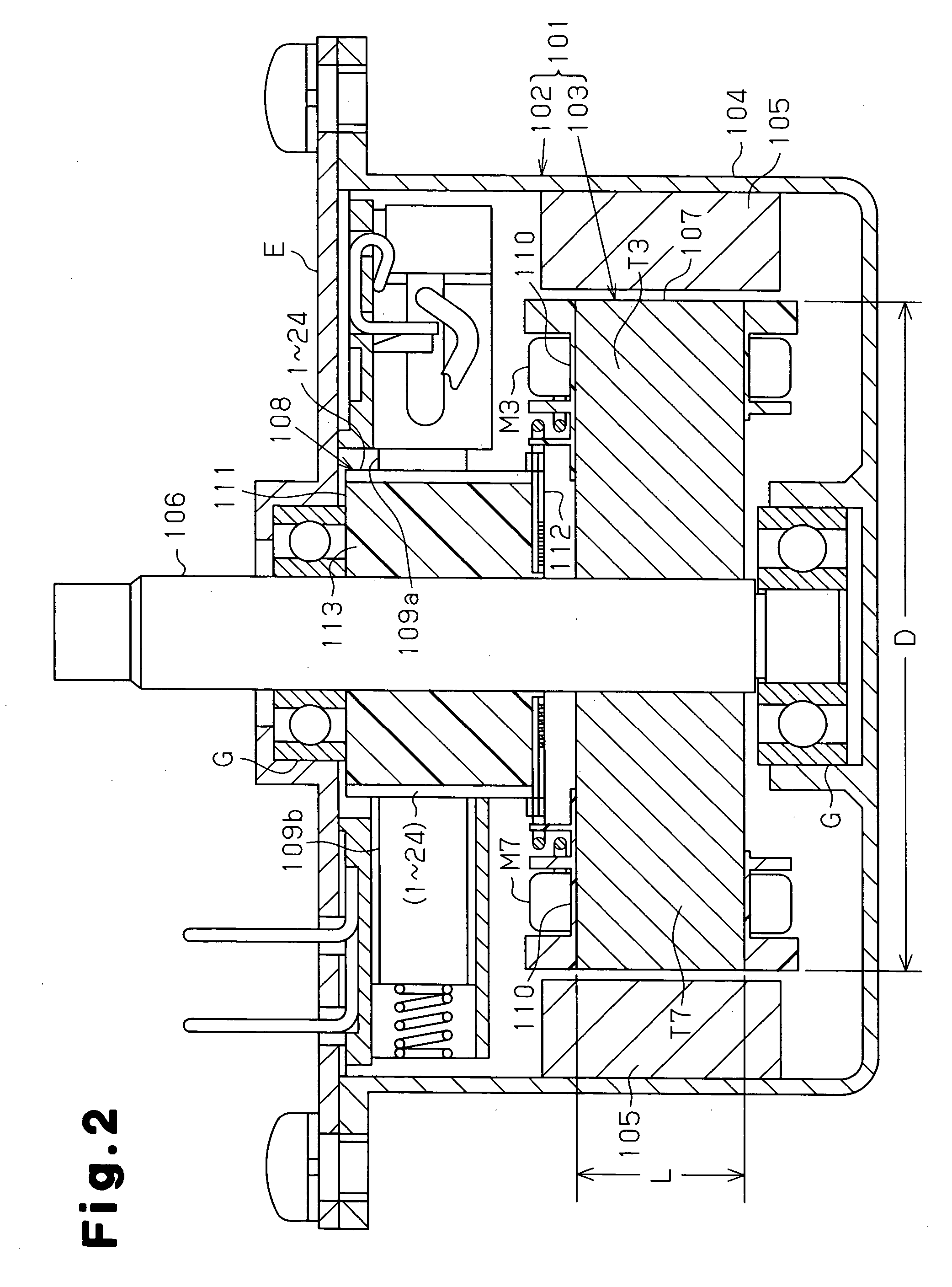
[0020] As shown in FIG. 1 and FIG. 2, a direct current motor 101 of the present embodiment includes a stator 102 and an armature (rotor) 103. The stator 102 includes a generally cylindrical yoke housing 104, which has a bottom wall at one end, and a plurality of (six in the present embodiment) magnets 105, which are fixed to the inner circumferential surface of the yoke housing 104 at equiangular intervals. The six magnets 105 form six magnetic poles. An end plate E is fixed to the yoke housing 104 so as to close the opening of the yoke housing 104. The yoke housing 104 and the end plate E form a motor housing.

[0021] The armature 103 includes a rotation shaft 106, an armature core 107 fixed to the rotation shaft 106, and a commutator 108 also fixed to the rotation shaft 106. The rotation shaft 106 is supported by bearings G received by the bottom wall of the yoke housing 104 and the...


PUM


Abstract

A stator of a direct current motor includes six magnetic poles. An armature of the direct current motor includes an armature core having eight slots, a plurality of windings wound around the armature core as concentrated windings, and a commutator having twenty-four segments connected to the windings. The plurality of windings are connected to one another to form a single closed loop. The direct current motor further includes an anode power supply brush and a cathode power supply brush that slidably contact the segments. The aspect ratio, which is the ratio of the diameter of the armature core with respect to the length in the axial direction of the armature core is set to a range of 3.2 through 5.6. This increases the constraint torque/mass ratio of the direct current motor.

Description

BACKGROUND OF THE INVENTION [0001] The present invention relates to a direct current motor including an armature core around which windings are wound as concentrated windings. [0002] A typical direct current motor includes an armature core including a plurality of teeth, and a plurality of windings wound around the teeth. A slot is formed between adjacent teeth. Such a direct current motor includes a type that has windings wound the plurality of teeth as distributed windings and a type that has windings wound around the plurality of teeth as concentrated windings. Each coil is arranged so as to traverse the plurality of slots in the distributed windings, whereas each coil is wound around only one tooth so that it does not traverse the plurality of slots in the concentrated windings. The occupation ratio of a winding in a slot is higher for concentrated windings than for distributed windings. [0003] In lieu of the typical direct current motor, which includes two magnetic poles (magne...

Claims


Application Information

Patent Timeline
IPC IPC(8): H02K1/00H01R39/04H01R39/32
CPCH02K23/30H02K23/04
Inventor ITO, YASUHIDESANTO, SHINJIKUWANO, MASAYUKIYAMAMOTO, TOSHIONAKANO, YOSHIKI
Owner DENSO CORP
Why Eureka
Try Eureka