Combination tool

a technology of combinator and tool, applied in the direction of multi-purpose tools, coupling device connections, pliers, etc., can solve the problems of inability to achieve the design that affords the capabilities of a compact, robust, low-profile design, and compromises the overall suitability and/or performance of the overall tool

Inactive Publication Date: 2007-04-12
SIEBECK ROY
View PDF35 Cites 23 Cited by
  • Summary
  • Abstract
  • Description
  • Claims
  • Application Information

AI Technical Summary

Problems solved by technology

The broad concept of a combination tool has been known for some time, but available combination tools have included features or capabilities that have compromised overall tool suitability and/or performance for a certain job (e.g., the jobs performed by linesman, electricians, and tinners), or that have not included features or capab...

Method used


Image

  • Combination tool
  • Combination tool
  • Combination tool

Examples


Embodiment Construction

[0012] As mentioned earlier, the present invention includes a variety of aspects, which may be combined in different ways. The following descriptions are provided to list elements and describe some of the embodiments of the present invention. These elements are listed with initial embodiments, however it should be understood that they may be combined in any manner and in any number to create additional embodiments. The variously described examples and preferred embodiments should not be construed to limit the present invention to only the explicitly described systems, techniques, and applications. Further, this description should further be understood to support and encompass descriptions and claims of all the various embodiments, systems, techniques, methods, devices, and applications with any number of the disclosed elements, with each element alone, and also with any and all various permutations and combinations of all elements in this or any subsequent application.

[0013] At lea...


PUM


Abstract

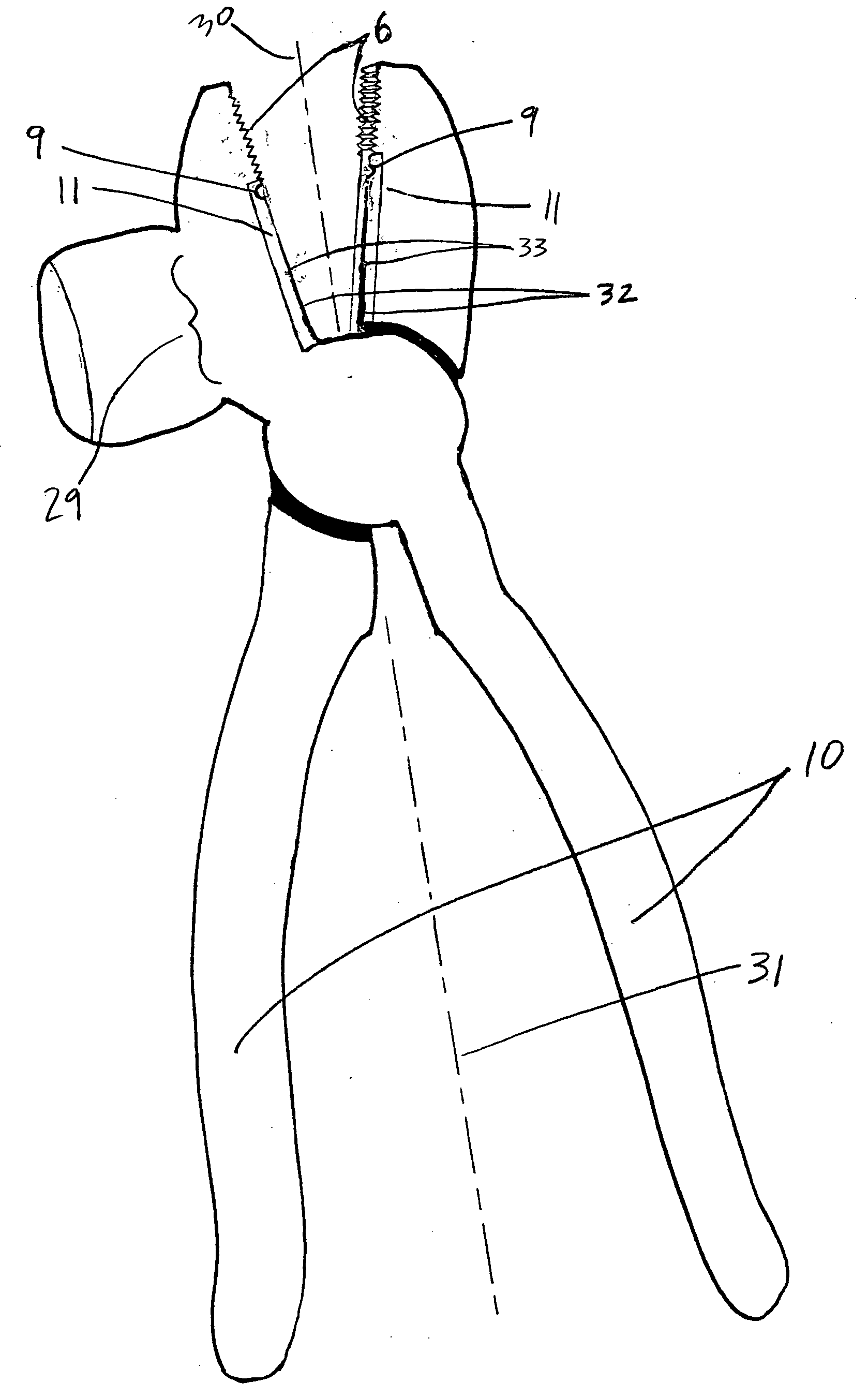
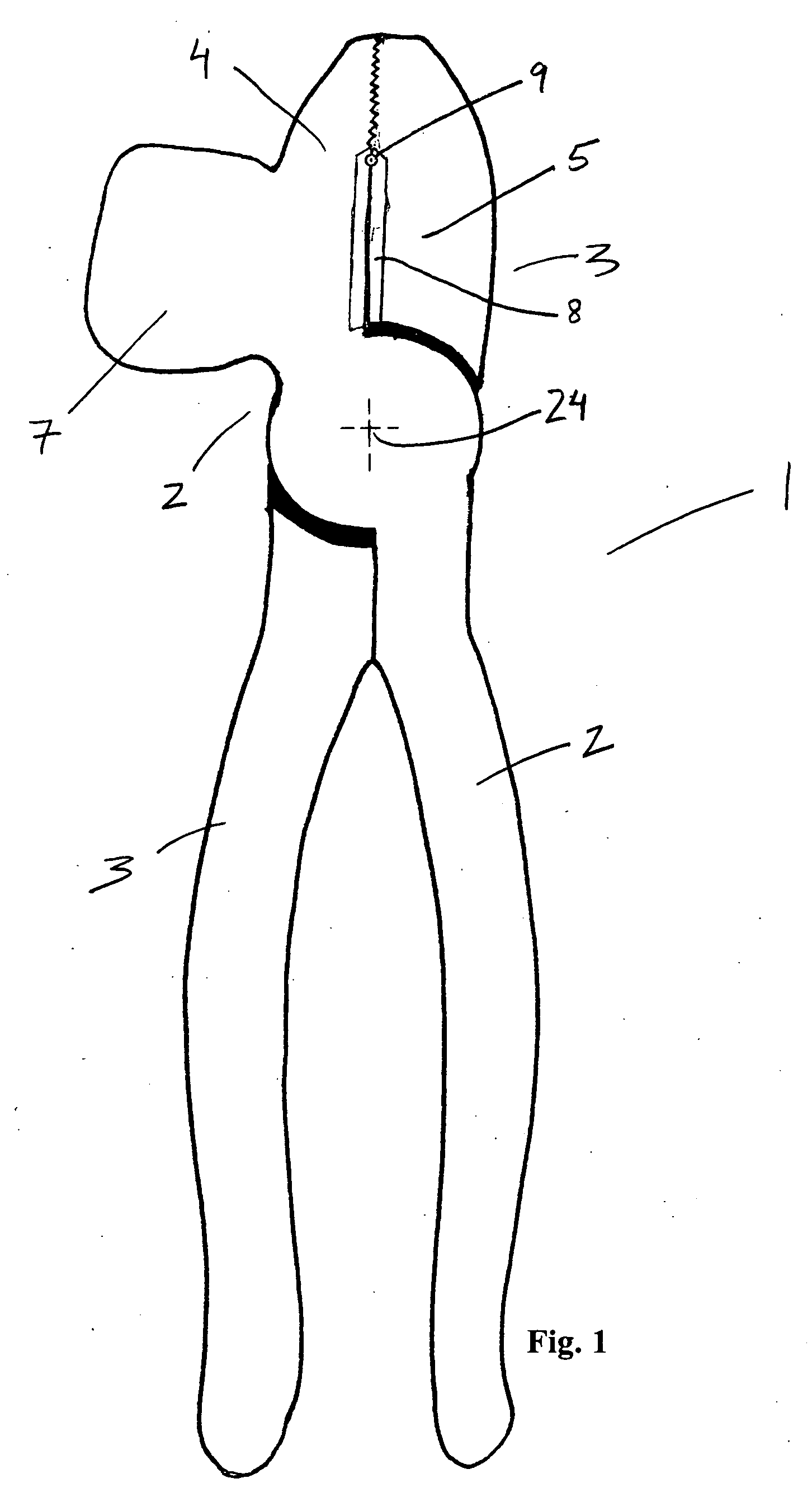
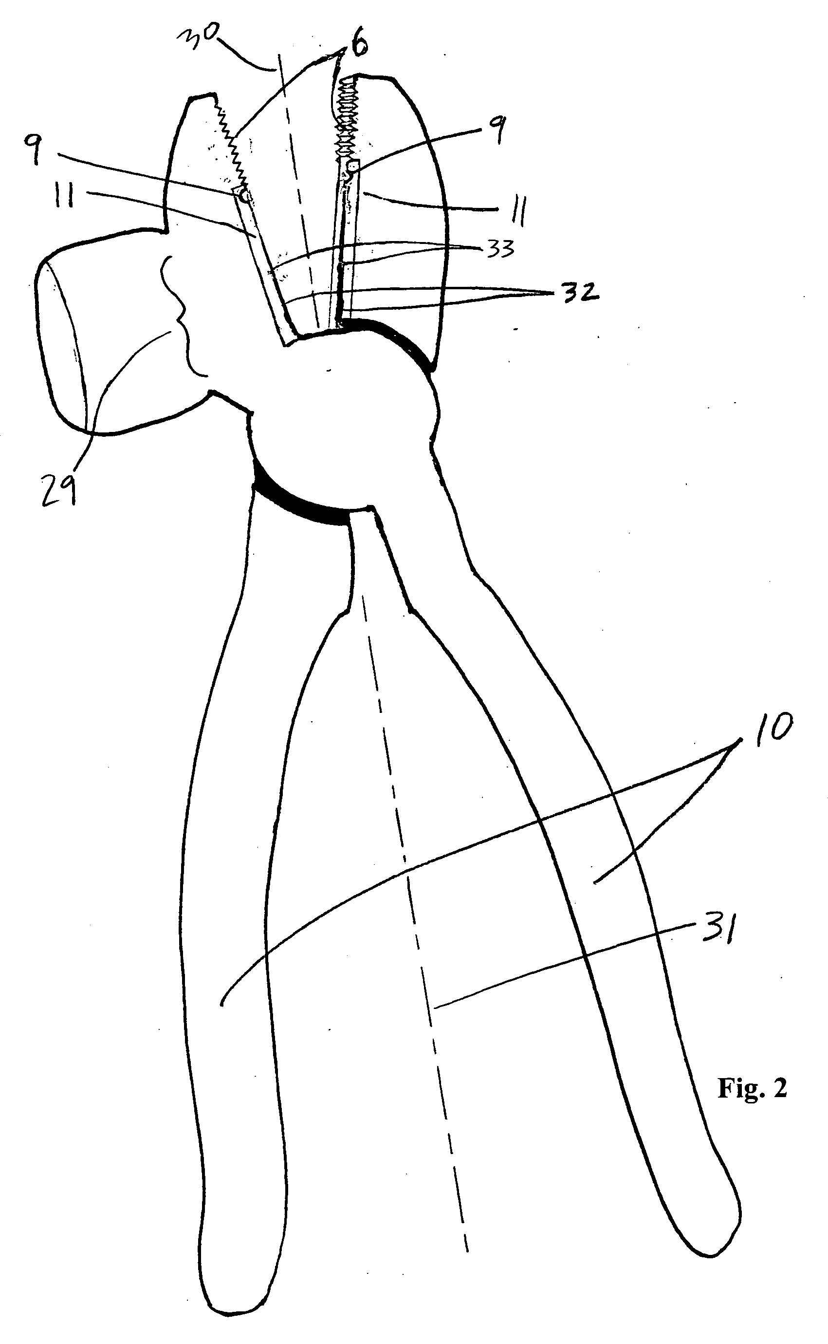
At least one embodiment of the inventive technology may be a combination tool apparatus that comprises a first tool part having a first plier jaw and a second tool part having a second plier jaw rotatable relative to an axis of rotation; compressive grip surfaces; a hammer head; a wire cutter element; a wire stripper element; and a handle. In certain of the many embodiments, the hammer head may be established within certain dimensional constraints relative to other part(s) of the tool, and/or the apparatus may not comprise a nail pulling claw.

Description

[0001] This application is continuation in part of international application PCT / US2005 / 020309 filed 08 Jun. 2005, now abandoned, which claims priority to U.S. Provisional Application No. 60 / 578,133, filed 8 Jun. 2004, each hereby incorporated herein by reference.TECHNICAL FIELD [0002] Generally, this invention relates to combination tool apparatus and related methods for accomplishing specific work tasks in an increased efficiency manner. Specifically, the invention focuses upon apparatus and related methods relative to a combination tool (and perhaps methods of use thereof) that is adapted to have certain alternate functionalities—wire cutting, wire stripping, hammering, and “pliering” and / or that has a hammer head that may be established within certain dimensional constraints relative to other part(s) of the tool. BACKGROUND [0003] The desire to improve work efficiency has been known for some years. The broad concept of a combination tool has been known for some time, but availab...

Claims


Application Information

Patent Timeline
IPC IPC(8): B25F1/00B25D1/04B25B7/22
CPCB25B7/22B25D1/04B25F1/006H01R13/6691H01R43/28
Inventor SIEBECK, ROY
Owner SIEBECK ROY
Why Eureka
Try Eureka