Commutator

Inactive Publication Date: 2007-04-12
ROBERT BOSCH GMBH
View PDF3 Cites 3 Cited by
  • Summary
  • Abstract
  • Description
  • Claims
  • Application Information

AI Technical Summary

Problems solved by technology

In operation, so-called brush noise can occur.
Moreover, among other factors, the imbalance that is due to dimensional inaccur

Method used


Image

  • Commutator
  • Commutator

Examples


Embodiment Construction

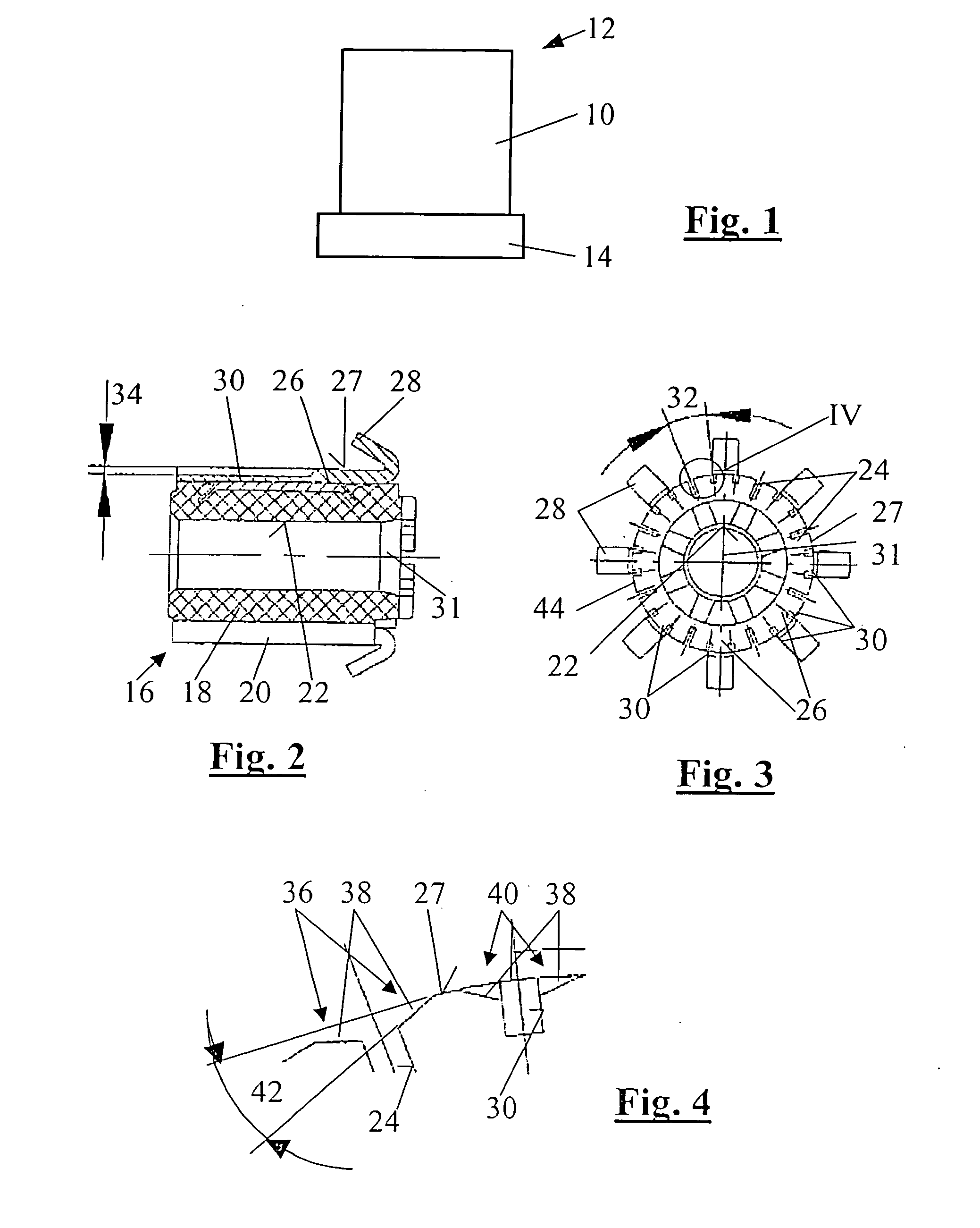
[0016] In FIG. 1, an electrical machine 10 is shown, which is part of a drive unit 12, which is preferably used in a motor vehicle. The drive unit 12 may be a power window system, a sliding groove drive, a drive train actuator, in particular a clutch actuator, or the like. A gear 14 is shown symbolically on the electrical machine 10.

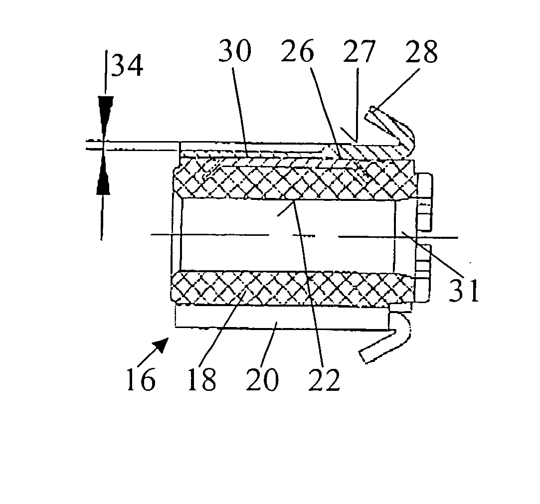
[0017] In FIGS. 2 through 4, a commutator 16 is shown. The commutator 16 has a cylindrical commutator core 18 of a thermosetting plastic, which is surrounded by a metal conductor sleeve (20), particularly of copper. A receiving bore 22, in which the armature shaft, not shown, of the electrical machine 10 is located, extends in the commutator core 18.

[0018] Longitudinally extending slots 24 separate the conductor sleeve 20 into individual laminations 26, insulated electrically from one another, that have contact faces 27 for brushes, not shown, of the electrical machine 10. On one end, each of the laminations 26 has a connecting hook 28. A connecting wi...


PUM


Abstract

A commutator for an electrical machine, which has a plurality of laminations that have contact faces and are separated from one another by slots in which, in the laminations, at least one groove is provided in the contact face, which groove extends essentially in the longitudinal direction of the respective lamination. As a result, the frequency with which the brushes are excited by the commutator can be increased, which has a favorable effect on noise.

Description

PRIOR ART [0001] The invention is based on a commutator for an electrical machine as generically defined by the preamble to claim 1. Such a commutator has a plurality of laminations, which have contact faces and are separated from one another by slots. [0002] In operation, so-called brush noise can occur. The commutator is the primary excitation source for this. On the one hand, the brush is entrained via the friction of the contact face of the commutator and brush. The brush is excited to oscillate by what is known as the stick-slip effect. Moreover, among other factors, the imbalance that is due to dimensional inaccuracies (such as errors of concentricity, eccentricity, lamination discontinuities, etc.), excites the commutator to oscillate. The lamination slots of the commutator have particular significance in this respect. Each slot—because of the radial prestressing—causes the brush edge to slip the slot upon a rotation and excites it to travel. After that, the brush is forced o...

Claims


Application Information

Patent Timeline
IPC IPC(8): H01R39/04H02K13/04H02K13/00H02K13/10
CPCH01R39/04H02K13/00
Inventor KUENZEL, GERALDBERNAUER, CHRISTOFBAUER, CHRISTIANSCHULZ, MARCUS
Owner ROBERT BOSCH GMBH
Why Eureka
Try Eureka