Time delay measurement

a time delay and measurement technology, applied in the field of time delay measurement, can solve the problems of reducing the accuracy of the local clock, unable to meet the needs of many applications, and inevitably far less accurate and stable than the ones residing, so as to reduce the noise, the effect of time delay determination and reducing the impact of nois

Inactive Publication Date: 2013-08-06
MITSUBISHI ELECTRIC CORP
View PDF13 Cites 2 Cited by
  • Summary
  • Abstract
  • Description
  • Claims
  • Application Information

AI Technical Summary

Benefits of technology

[0015]Such a technique can be used for measuring the delay between the signals. If the technique involves samples only obtained in response to chip boundaries between bits of the first signal which have the same state, then a representation referred to below as type-b is obtained. This has leading and trailing edges at positions either or both of which can be determined and used to discover the delay between the signals. The leading and trailing edges are widely separated, which can be advantageous in some systems to mitigate the problems which can arise in detecting the edges due to noise and bandwidth limitations.
[0016]If the technique involves samples obtained in response to chip boundaries between bits of the first signal which have the same state, and also in response to chip boundaries between different states, then a representation referred to below as type-c is obtained. This has closer, but substantially higher, leading and trailing edges at positions, thus enabling time delay determination which is less affected by noise than when using a type-b representation.
[0017]In both cases, enhancement of the edges can be obtained by deriving values which are not simply obtained by summing samples, but instead by summing the differences between time-separated samples, thereby effectively performing a differentiation. Thus, for example, each selected chip boundary can cause two time-separated samples to be derived, and the difference therebetween to be added to values accumulated in response to previous chip boundaries. Alternatively, the samples obtained for each introduced delay can be subtracted from the samples from the next introduced delay. As a further alternative, the second signal can be differentiated before sampling.
[0019]The invention can be used to advantage for processing of signals in GPS and other similar positioning systems, for example for tracking loop phase error discriminator for DLL code alignment or LoS signal timing recovery from multipath contamination.

Problems solved by technology

Due to cost and size considerations, many GPS receivers make use only of cheap local clock sources that are inevitably far less accurate and stable than the ones residing in the satellites.
This reduced accuracy of the local clock, however, can be easily calibrated out by the inclusion of an additional satellite ranging in the receiver position determination procedure.
Although it is desirable for a GPS receiver to receive only the direct path (i.e. line-of-sight, LoS) signal from each of the navigation satellites in its view, this is hardly practical in many application scenarios.
The multipath signals arrive at the receiver after the direct path signal and combine with the latter to form a distorted version which adversely affects the DLL loop operations, causing possibly a synchronisation offset between the satellite transmission code phase and that of the locally generated code sequence.
This synchronisation offset contributes directly to a ranging error in measuring the distance between the satellite and the receiver, leading to the receiver position fix having a deviation from the true receiver position in a typical magnitude of a few to tens of metres.

Method used


Image

  • Time delay measurement
  • Time delay measurement
  • Time delay measurement

Examples


Embodiment Construction

[0035]The invention will be described in the context of the processing of incoming GPS navigation signals and making a signal arrival time measurement of the LoS signal. However, many alternative implementations are possible.

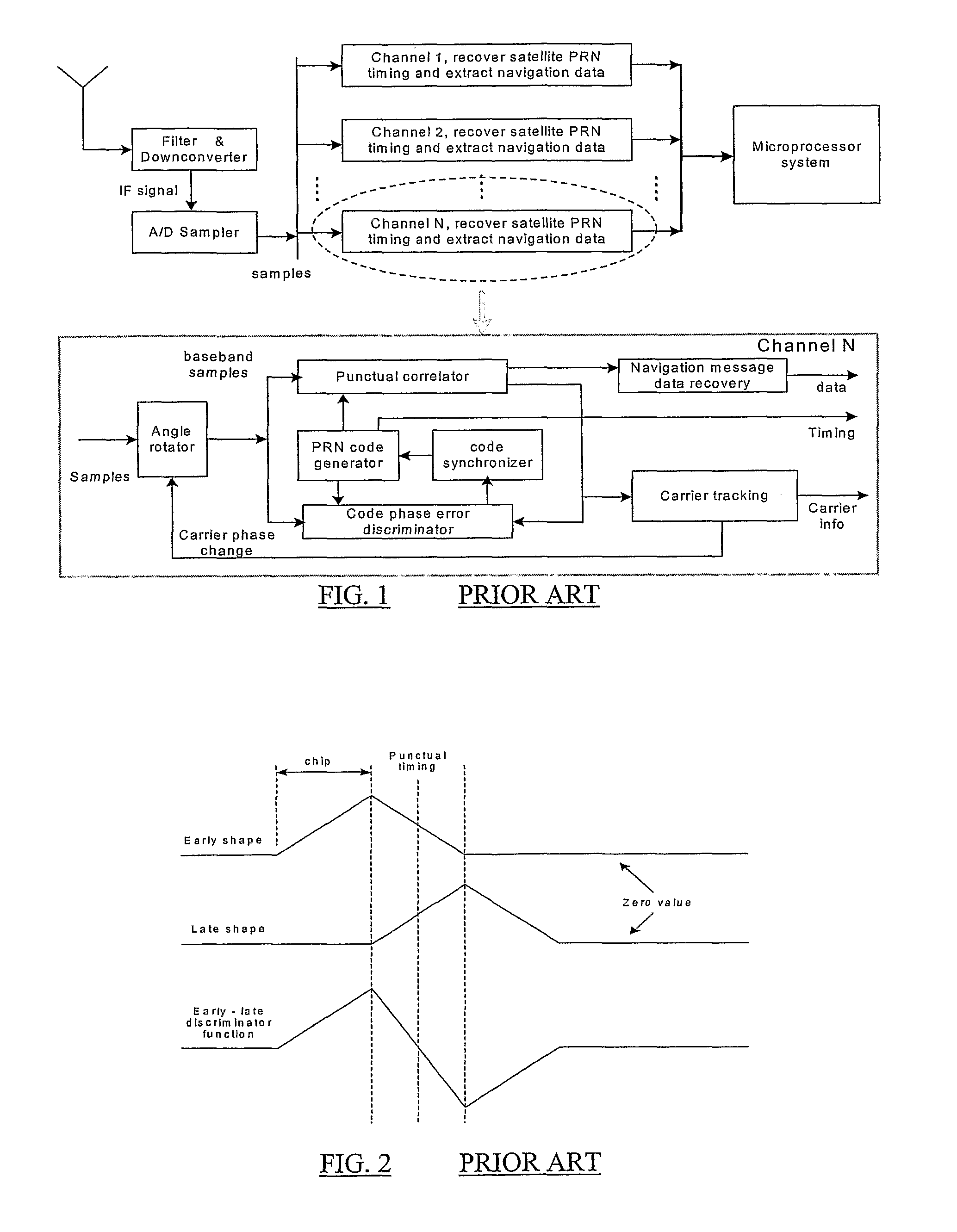
[0036]FIG. 1 is a simplified block diagram illustrating a typical prior art receiver structure of a GPS receiver for processing the incoming signal. Here, the PRN code type is assumed to be of the public civilian C / A (C / A=coarse access or civilian access) code for simplicity. The core components in the figure, as far as the signal processing aspects are concerned, are the multiple identical channels. Each tracks a given satellite by configuring the PRN code generator to produce the code sequence corresponding to that given satellite. As shown in the figure, the received radio frequency signal is sampled after down-conversion and the samples are fed to multiple channels for independent channelized processing, which is possible due to the orthogonal property betwe...


PUM


Abstract

A method of processing first and second corresponding signals having a delay therebetween. The method includes introducing a plurality of different delays between the first and second signals, successive delay amounts differing from each other by less than the interval between chip boundaries, and for each introduced delay, summing samples of the second signal which are obtained at the times of, at least, chip boundaries between bits of the first signal which have the same state, to obtain a value; thereby to obtain a representation of how the value varies according to the introduced delay, which representation contains a level change associated with an introduced delay which bears a predetermined relationship to the delay between the first and second signals.

Description

BACKGROUND OF THE INVENTION[0001]1. Field of the Invention[0002]The invention relates generally to time delay measurement. It is particularly, but not exclusively, applicable to systems that require an accurate measurement of the arrival time of a spread-spectrum radio signal and, in particular, to global navigation satellite system (GNSS) receivers for which the time measurement is essential and ideally should be insensitive to distortions in the received radio signal caused by surrounding reflections (i.e. the multipath phenomenon).[0003]2. Description of the Prior Art[0004]For years spread-spectrum radio signals have been exploited for ranging applications. One well-known example is the global positioning system (GPS) that comprises a number of earth-orbiting satellites that transmit navigational spread-spectrum radio signals. These navigational radio signals are L-band carriers synchronously modulated with satellite-specific, pseudo-random-noise (PRN) code sequences in sync with...

Claims


Application Information

Patent Timeline
Patent Type & Authority Patents(United States)
IPC IPC(8): H04L27/06G01S19/30
CPCG01S19/30G01S5/14G01S19/13
Inventor CHEN, NONGJI
Owner MITSUBISHI ELECTRIC CORP
Why Eureka
Try Eureka