Multi-touch system and method for controlling liquid crystal capacitors to reduce touch sensing interference

a multi-touch system and capacitor technology, applied in the field of touch panels, can solve the problems of difficult capacitive detection, wrong decision, and significant influence of capacitor csub>lc/sub>, and achieve the effects of reducing touch sensing interference, touch sensing technology, and reducing the affection of nois

Active Publication Date: 2017-05-02
FOCALTECH SYST CO LTD
View PDF2 Cites 2 Cited by
  • Summary
  • Abstract
  • Description
  • Claims
  • Application Information

AI Technical Summary

Benefits of technology

[0011]The object of the present invention is to provide a multi-touch system and method for controlling liquid crystal capacitors to reduce touch sensing interferences, which can reduce the affection of the noises produced by the LCD panel in touch sensing and allow the touch sensing technology to be more steady in a portable application for prolonging the lifetime.

Problems solved by technology

When capacitance of a liquid crystal capacitor is not fixed, it is difficult to perform a capacitive detection because the finger capacitance Cp is connected to the capacitor CLC and change of its capacitance change is small, resulting in that the influence of the capacitor CLC is significant.
Since the change of the capacitance Cp is small, it is sensitive to noises, and a wrong decision may be made.
Thus, when the touch panel is mounted on the LCD panel, it is likely to be affected by the noises produced by the LCD panel.
However, in addition to the increased cost or panel thickness, such a method can be used only in the out-cell touch technology.
Moreover, the noise isolation from the display panel is not satisfactory.
In the capacitive touch technology, if capacitance of the liquid crystal capacitor CLC is not fixed, sensing a capacitance Cp becomes difficult, and then a wrong decision may occur.
As shown in FIG. 5, when the liquid crystal capacitors CLC are changed while a typical touch sensing is performed, it causes a reduction or increase of the raw data extracted on touching, resulting in making a wrong decision and coordinate sway.

Method used


Image

  • Multi-touch system and method for controlling liquid crystal capacitors to reduce touch sensing interference
  • Multi-touch system and method for controlling liquid crystal capacitors to reduce touch sensing interference
  • Multi-touch system and method for controlling liquid crystal capacitors to reduce touch sensing interference

Examples


Embodiment Construction

[0025]FIG. 6 is a schematic diagram of a multi-touch system 600 according to a preferred embodiment of the invention. In FIG. 6, the system 600 includes a touch LCD panel 610 and a touch display control subsystem 620.

[0026]The touch LCD panel 610 has a thin film transistor (TFT) layer 611, a sensing electrode layer 613, and a common voltage layer (Vcom) 615 formed in a stacking manner. The stacking manner can be the TFT layer 611 at the bottom, the common voltage layer (Vcom) 615 in the middle, and the sensing electrode layer 613 at the top of the touch LCD panel 610.

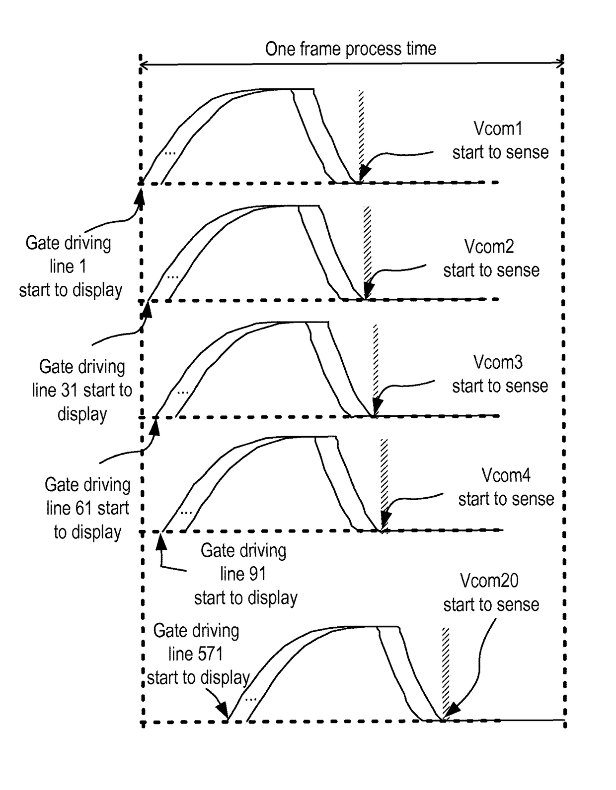
[0027]The TFT layer 611 has K gate driving lines (G1-G600) and L source driving lines (SOURCE1-SOURCE800) in order to drive display transistors Tr and capacitors CLC corresponding to pixels on the LCD panel, according to a display pixel signal and a display driving signal, for performing a display driving, where K, L are each a positive integer. For convenient description, in this embodiment, we have K=600, and L=800.

[0...


PUM

PropertyMeasurementUnit
voltageaaaaaaaaaa
voltageaaaaaaaaaa
areaaaaaaaaaaa

Abstract

A multi-touch system for controlling liquid crystal capacitors to reduce touch sensing interferences includes K gate driving lines, which are divided into N groups each corresponding to a common voltage conductive line. When a display driving signal is applied to an i-th group of gate driving lines for performing a display driving, the liquid crystal capacitor corresponding to the i-th group is set to a predetermined voltage, where i=1 to N. Finally, a touch driving signal is applied to an i-th common voltage conductive line corresponding to the i-th group for sensing touch points, so as to reduce touch sensing affections caused by noises of the liquid crystal display.

Description

BACKGROUND OF THE INVENTION[0001]1. Field of the Invention[0002]The present invention relates to the technical field of touch panels and, more particularly, to a multi-touch system and method for controlling liquid crystal capacitors to reduce touch sensing interference.[0003]2. Description of Related Art[0004]Typically, the capacitance changes of liquid crystal capacitors CLC in liquid crystal displays (LCDs) are used to achieve a display on the panels. The change of a liquid crystal capacitor is varied with different voltages to thus have the corresponding values. FIG. 1 is a graph of capacitance CLC vs voltage V for a liquid crystal capacitor. In FIG. 1, the voltage V is changed from zero to 5V. The relationship between capacitance CLC and voltage V is obtained by controlling the voltage V as shown in FIG. 1.[0005]Accordingly, when the capacitance of the LC capacitor CLC on the LCD panel is changed, a capacitive touch sensing is operated, which is likely to cause a touch sensing ...

Claims


Application Information

Patent Timeline
Patent Type & Authority Patents(United States)
IPC IPC(8): G06F3/041G09G3/36G06F3/044G02F1/1333
CPCG06F3/0412G02F1/13338G06F3/044G06F3/0418G09G3/3648G06F2203/04103G06F2203/04104G09G2354/00G06F3/04184G06F3/0443G06F3/0446
Inventor HUANG, HSIN-MAOYU, HSIANG-CHENGHUANG, SHIH-HSIN
Owner FOCALTECH SYST CO LTD
Why Eureka
Try Eureka