Liquid ejecting apparatus and drive circuit

a technology of drive circuit and ejector, which is applied in the direction of printing, etc., can solve the problems of reducing the reproducibility of drive signal waveform and reducing print quality, and achieve the effect of less affected by noise or the lik

Active Publication Date: 2017-08-31
SEIKO EPSON CORP
View PDF0 Cites 2 Cited by
  • Summary
  • Abstract
  • Description
  • Claims
  • Application Information

AI Technical Summary

Benefits of technology

[0010]An advantage of some aspects of the invention is to provide a liquid ejecting apparatus and a drive circuit which are les

Problems solved by technology

Accordingly, when transistors of two or more drive circuits are turned on simultaneously, other circuits are affected by noise or the like caused

Method used


Image

  • Liquid ejecting apparatus and drive circuit
  • Liquid ejecting apparatus and drive circuit
  • Liquid ejecting apparatus and drive circuit

Examples


Embodiment Construction

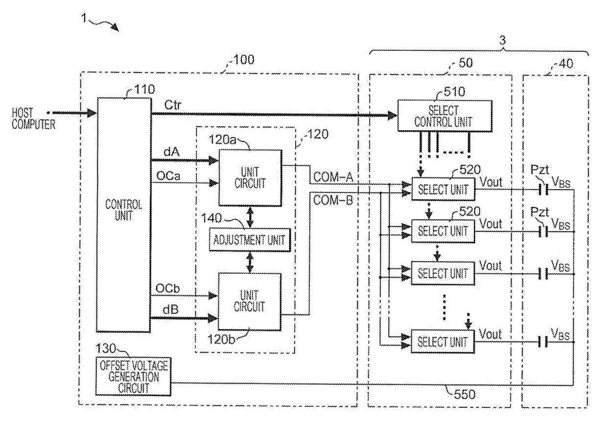
), one of the high-side transistor and the low-side transistor performs a linear operation during a period in which the voltage of the drive signal COM-A (COM-B) is constant and the other transistor is turned off, and one of the high-side transistor and the low-side transistor performs a switching operation during a period in which the voltage of the drive signal changes and the other transistor is turned off. Accordingly, the drive circuit (Example 1, Example 2) can reduce power consumption, compared with the class D amplification.

[0263]In addition, the class D amplification requires a low pass filter (LPF) demodulating a signal which is switched by the high-side transistor and the low-side transistor, particularly, an inductor such as a coil, but the drive circuit (Example 1, Example 2) does not require the LPF. Accordingly, according to the drive circuit (Example 1, Example 2), it is possible to reduce power which is consumed in the LPF, compared with the class D amplification ci...


PUM


Abstract

A liquid ejecting apparatus includes an ejecting unit that includes a piezoelectric element which is displaced by a first drive signal or a second drive signal; a first unit circuit that generates the first drive signal by using a first pair of transistors; a second unit circuit that generates the second drive signal by using a second pair of transistors; and an adjustment unit that delays at least one of a first control signal and a second control signal to supply the delayed control signal to a corresponding unit circuit, in a case where timing when a level of the first control signal for controlling the first pair of transistors changes and timing when a level of the second control signal for controlling the second pair of transistors changes are within a threshold time, and in a case where a predetermined condition is satisfied.

Description

[0001]The entire disclosure of Japanese Patent Application No. 2016-034999, filed Feb. 26, 2016 is expressly incorporated by reference herein.BACKGROUND[0002]1. Technical Field[0003]The present invention relates to a liquid ejecting apparatus and a drive circuit.[0004]2. Related Art[0005]An ink jet printer (liquid ejecting apparatus) which uses a piezoelectric element, for example, a piezo element is known as a printing apparatus which prints an image or a text by ejecting ink. Piezoelectric elements are provided in correspondence with multiple nozzles in a head unit, each of the piezoelectric elements is driven in response to a drive signal, and thereby, a predetermined amount or ink (liquid) is ejected from the nozzle at predetermined timing to form dots. Since the piezoelectric element is electrically a capacitive load like a capacitor, a sufficient current is required to operate the piezoelectric element of each nozzle.[0006]Accordingly, a liquid ejecting apparatus has a configu...

Claims


Application Information

Patent Timeline
IPC IPC(8): B41J2/045
CPCB41J2/04581B41J2/04573B41J2/04541B41J2/04588B41J2/04593B41J2/04596
Inventor YAMADA, TOMOKAZU
Owner SEIKO EPSON CORP
Why Eureka
Try Eureka