Non-pneumatic wheel

a non-pneumatic, wheel technology, applied in the direction of wheel protection, high-resiliency wheels, vehicle components, etc., can solve the problems of releasing air, wheel non-functionality, and affecting the safety of drivers,

Active Publication Date: 2007-04-26
THE BOEING CO
View PDF26 Cites 42 Cited by
  • Summary
  • Abstract
  • Description
  • Claims
  • Application Information

AI Technical Summary

Problems solved by technology

A pneumatic wheel develops a “flat tire” when a foreign object punctures the outer tire, allowing the air to escape, rendering the wheel non-functional.
Further, a sudden release of air when the vehicle is moving, known as a “blow-out,” can be hazardous because control of the vehicle can quickly be lost.
Since vehicles do not operate properly with flat tires, flat tires r

Method used


Image

  • Non-pneumatic wheel
  • Non-pneumatic wheel
  • Non-pneumatic wheel

Examples


Embodiment Construction

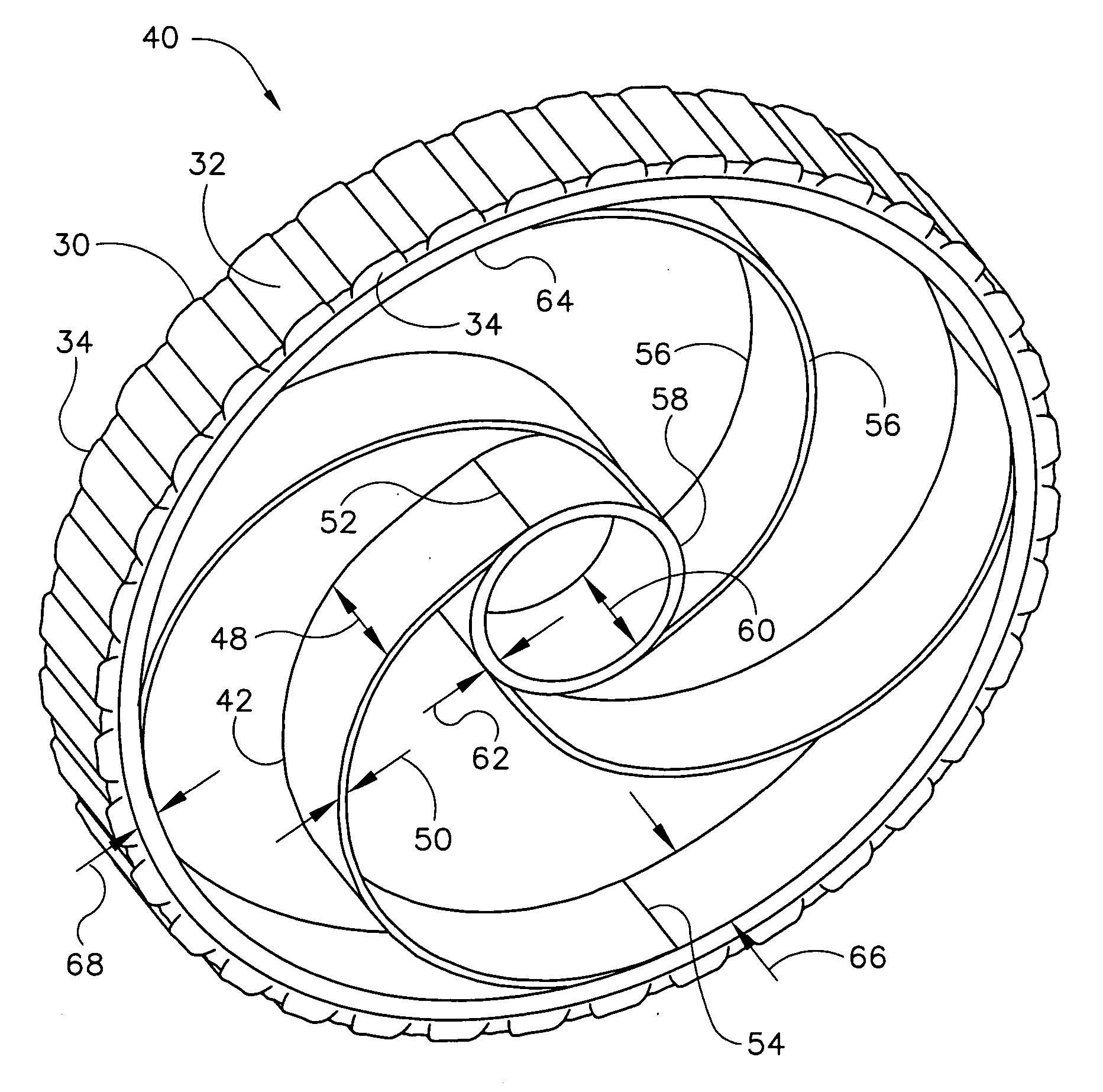
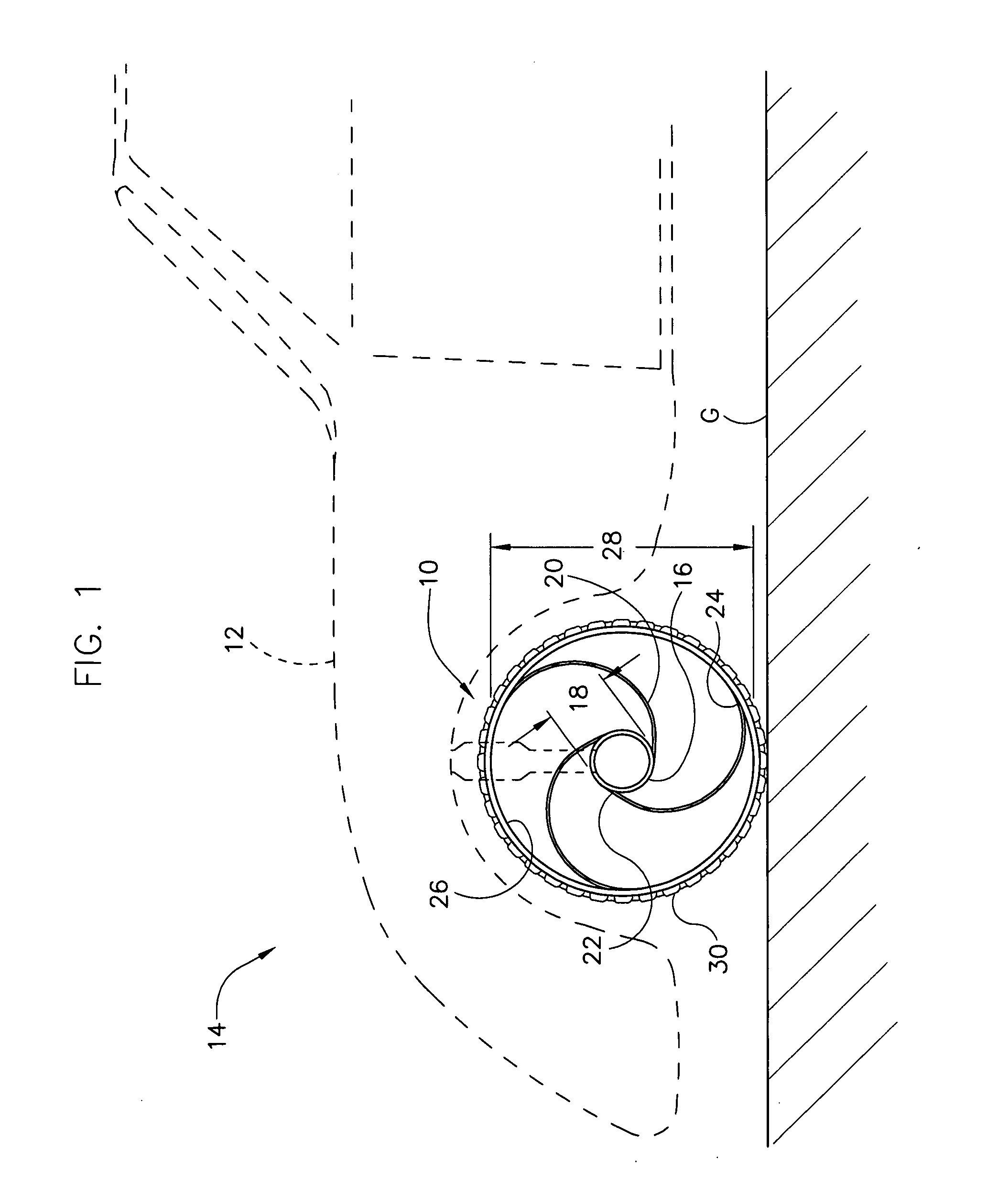
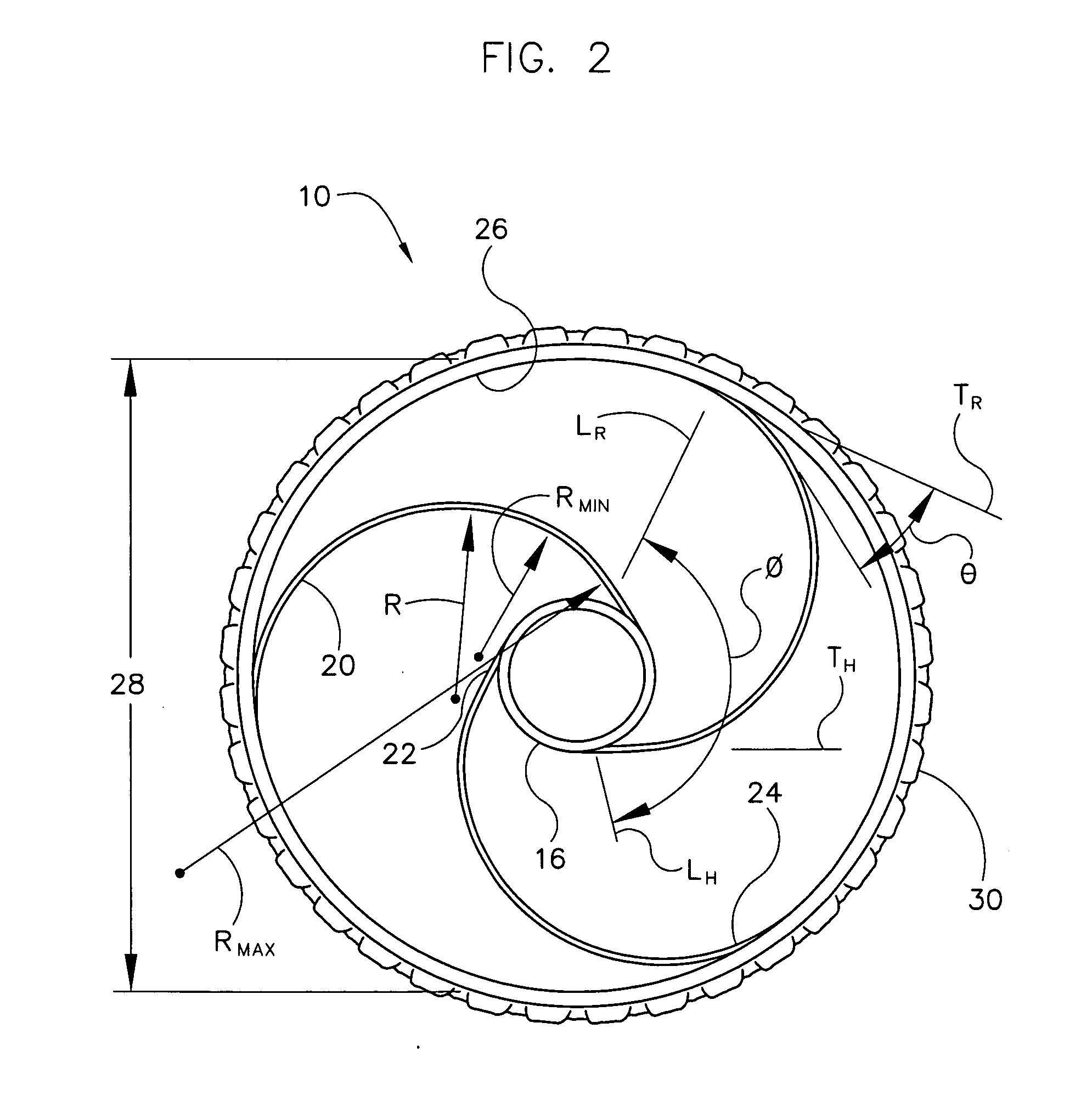
[0014] Referring to the drawings, and more particularly to FIG. 1, a wheel according to a first embodiment of the present invention is designated in its entirety by reference number 10. The wheel 10 may be rotatably mounted to a body 12 of an automobile, generally designated 14. Although the wheel 10 is shown mounted on an automobile 14, the wheel 10 may be mounted on a wide variety of vehicles, such as aircraft, bicycles, all-terrain vehicles, and wheelchairs. Further, the wheel 10 may be used in ways other than for transporting a vehicle 14. For example, the wheel 10 may be used as an internal component for machinery (not shown) or wherever traditional wheels are used. The wheel 10 includes an annular hub 16 rotatably connected to the body 12. Although the hub 16 may be made of other materials without departing from the scope of the present invention, in one embodiment the hub is made of steel. Although the hub 16 may have other shapes without departing from the scope of the prese...


PUM


Abstract

A wheel including an annular hub and a plurality of curved spokes extending radially outward from the hub. Each spoke has an inner base adjacent the hub and an outer tip opposite the base. The wheel further includes an annular rim concentric with the hub and connected to the spokes adjacent their tips.

Description

BACKGROUND OF THE INVENTION [0001] The present invention relates to wheels and, more particularly, to non-pneumatic wheels for vehicles. [0002] Until recently, conventional wheels for vehicles, such as automobiles, included an outer tire filled with air. These conventional wheels are commonly referred to as pneumatic wheels because they require air to function properly. A pneumatic wheel develops a “flat tire” when a foreign object punctures the outer tire, allowing the air to escape, rendering the wheel non-functional. Further, a sudden release of air when the vehicle is moving, known as a “blow-out,” can be hazardous because control of the vehicle can quickly be lost. Since vehicles do not operate properly with flat tires, flat tires require repair or replacement. There is a need for a practical high-performance airless or non-pneumatic wheels. [0003] Within the last few years, several non-pneumatic wheel designs have surfaced. However, these designs have various limitations. For ...

Claims


Application Information

Patent Timeline
IPC IPC(8): B60B9/04
CPCB60B7/0086B60B9/26B60B2900/513
Inventor GABRYS, JONATHAN W.LEE, RYAN S.
Owner THE BOEING CO
Why Eureka
Try Eureka