Supercharge Your Innovation With Domain-Expert AI Agents!

Arc plate with runner, and arc chute and electrical switching apparatus incorporating same

a technology of arc plate and runner, which is applied in the direction of air-break switch, high-tension/heavy-dress switch, electrical apparatus, etc., can solve the problems of damage to nearby separable contacts, unsatisfactory arc, and destruction of moveable and stationary contacts,

Inactive Publication Date: 2007-05-03
EATON CORP
View PDF15 Cites 1 Cited by
  • Summary
  • Abstract
  • Description
  • Claims
  • Application Information

AI Technical Summary

Benefits of technology

The present invention provides an arc plate for an electrical switching apparatus that is designed to attract and direct the arc away from the separable contacts of the apparatus. The arc plate includes a plate member and an arc runner that works to draw the arc towards the back of the arc chute and away from the contacts. This helps to improve the safety and reliability of the electrical switching apparatus. The arc chute also includes a support structure and a plurality of arc plates that are supported in spaced relation to the contacts, with at least some of the arc plates including an integral arc runner to direct the arc towards the second end of the arc plate. This design helps to increase the efficiency of the arc chute and improve the overall performance of the electrical switching apparatus.

Problems solved by technology

Such an arc is undesirable for a number of reasons.
Additionally, the electrical arc extending between the contacts often results in vaporization or sublimation of the contact material itself, eventually resulting in destruction or pitting of the moveable and stationary contacts.
However, the arc has a tendency to follow the inside edge of the arc chute adjacent the separable contacts which can cause heavy erosion of the arc plates and damage to the nearby separable contacts.

Method used


Image

  • Arc plate with runner, and arc chute and electrical switching apparatus incorporating same
  • Arc plate with runner, and arc chute and electrical switching apparatus incorporating same
  • Arc plate with runner, and arc chute and electrical switching apparatus incorporating same

Examples


Embodiment Construction

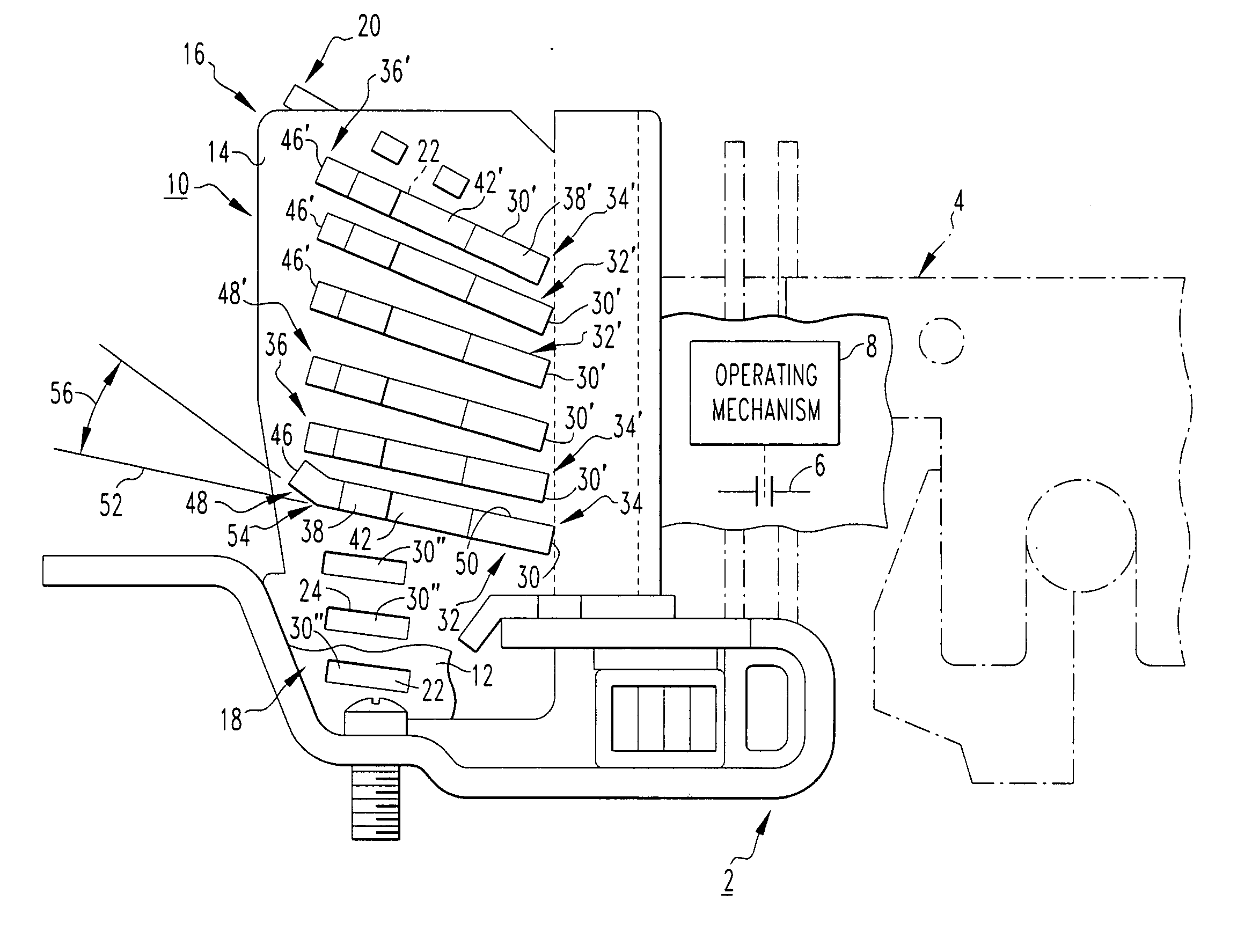
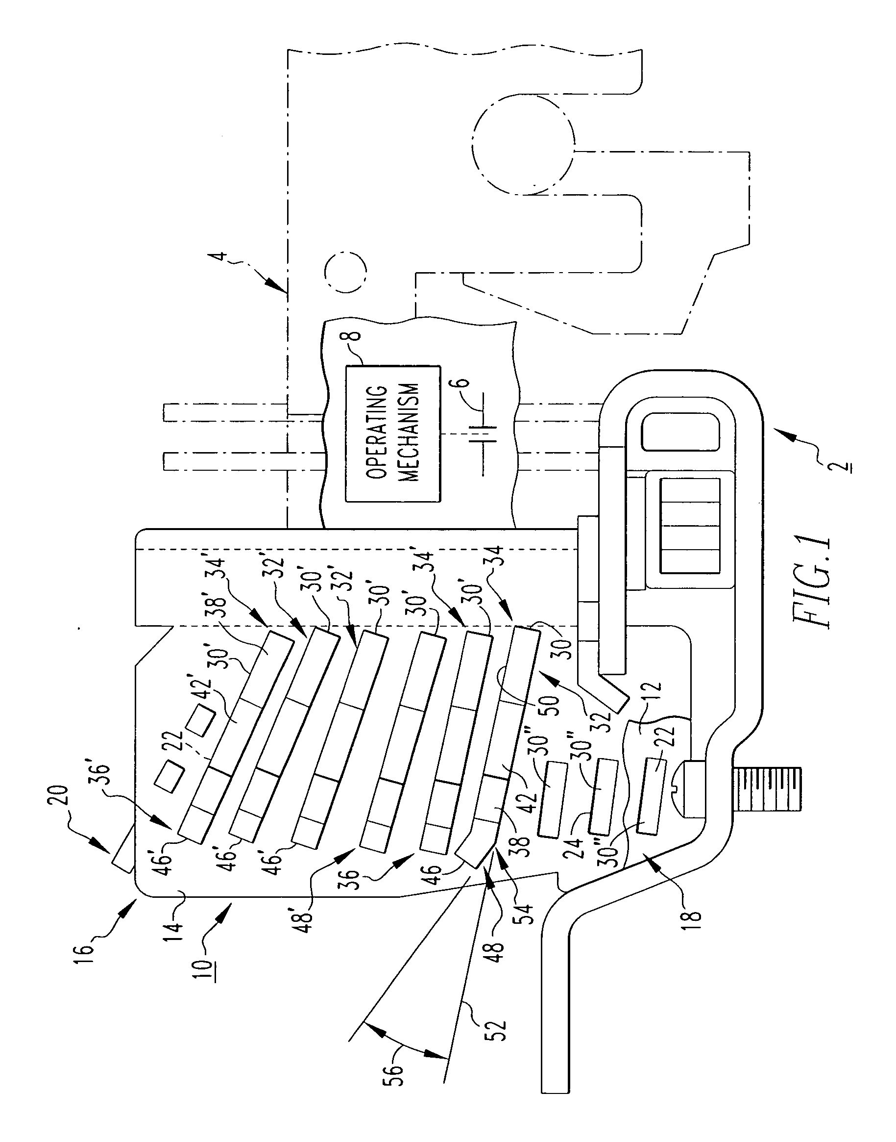
[0024] For purposes of illustration, the invention will be described as applied to the arc chute of a molded case circuit breaker, although it will become apparent that it could also be applied to a wide variety of electrical switching apparatus (e.g., without limitation, circuit switching devices and other circuit interrupters such as contactors, motor starters, motor controllers and other load controllers) having an arc chute with a plurality of arc plates.

[0025] Directional phrases used herein, such as, for example, left, right, top, bottom, front, back and derivatives thereof, relate to the orientation of the elements shown in the drawings and are not limiting upon the claims unless expressly recited therein.

[0026] As employed herein, the statement that two or more parts are “coupled” together shall mean that the parts are joined together either directly or joined through one or more intermediate parts.

[0027] As employed herein, the term “secondary” shall refer to a component...


PUM


Abstract

An arc plate is for a circuit breaker including a housing, a pair of separable contacts enclosed within the housing and an arc chute. The arc chute includes a plurality of the arc plates supported in spaced relation between opposing side walls. Each arc plate includes a first end disposed proximate the separable contacts, and a second end distal from the separable contacts. An arc runner, such as an integral tab extension, protrudes from the second end of the arc plate in order to draw the arc away from the first end thereof. The integral tab extension of at least one arc plate includes a bend such that the extension forms an angle of between about 20 degrees and about 50 degrees with respect to the plane of the arc plate, in order to direct the arc toward the second ends of adjacent arc plate.

Description

CROSS-REFERENCE TO RELATED APPLICATION [0001] This application is related to commonly assigned, concurrently filed U.S. patent application Ser. No. ______, filed ______, 2005, entitled “Secondary Arc Chute and Electrical Switching Apparatus Incorporating Same” (Attorney Docket No. 03-EDP-106).BACKGROUND OF THE INVENTION [0002] 1. Field of the Invention [0003] The present invention relates generally to electrical switching apparatus and, more particularly, to arc plates for the arc chute of a circuit breaker. The invention also relates to arc chutes for electrical switching apparatus and to electrical switching apparatus having arc chutes. [0004] 2. Background Information [0005] Circuit breakers and other electrical switching apparatus (e.g., without limitation, circuit switching devices and other circuit interrupters such as contactors, motor starters, motor controllers and other load controllers) typically include a set of stationary electrical contacts and a set of moveable electr...

Claims


Application Information

Patent Timeline
Patent Type & Authority Applications(United States)
IPC IPC(8): H01H33/00
CPCH01H9/36H01H9/46
Inventor ZINDLER, MARK O.
Owner EATON CORP
Features
  • R&D
  • Intellectual Property
  • Life Sciences
  • Materials
  • Tech Scout
  • Unparalleled Data Quality
  • Higher Quality Content
  • 60% Fewer Hallucinations
Learn More