Embedding and Reading Codes on Objects

a technology of machine-readable codes and objects, applied in the field of embedding and reading machine-readable codes on objects, can solve the problems of code not being aesthetically pleasing, occupying a dedicated portion of the physical object in which they reside, and needing to locate the code on a dedicated portion of the obj

Active Publication Date: 2007-05-17
DIGIMARC CORP
View PDF98 Cites 171 Cited by
  • Summary
  • Abstract
  • Description
  • Claims
  • Application Information

AI Technical Summary

Problems solved by technology

While these forms of machine-readable identification are widely used and effective for many applications, they all have the disadvantage that they must occupy a dedicated portion of the physical object that they reside on.
For many applications, however, the need to locate the code on a dedicated portion of the object is a significant drawback.
One drawback is that it requires the user to position the object so that the portion carrying the code can be read.
Another drawback is that the code is not aesthetically pleasing, and may detract from the overall appearance of the object.
In addition, the placement of the code may require an expensive and cumbersome manufacturing and application process.
In some cases, however, it is a disadvantage for the code to be visually perceptible.
As noted above, one drawback is that it detracts from the aesthetic appearance of the object.
Another drawback is that it may be more likely to be tampered with.

Method used


Image

  • Embedding and Reading Codes on Objects
  • Embedding and Reading Codes on Objects
  • Embedding and Reading Codes on Objects

Examples


example implementations

of Digital Image Watermark Embedder and Reader

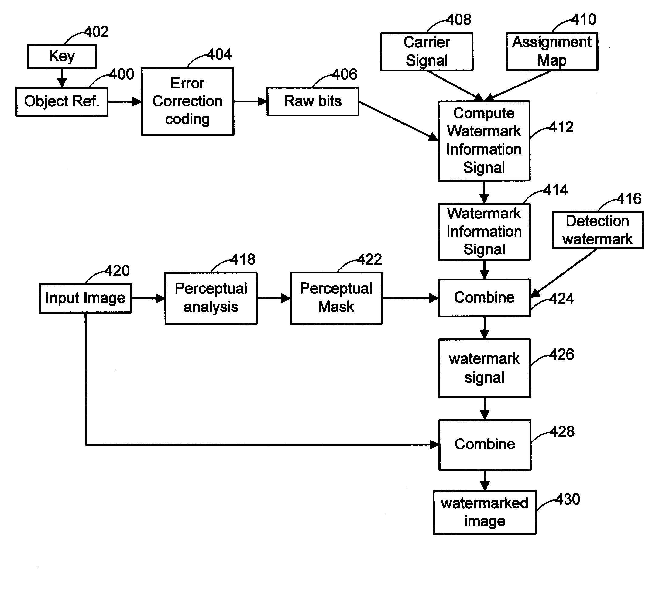
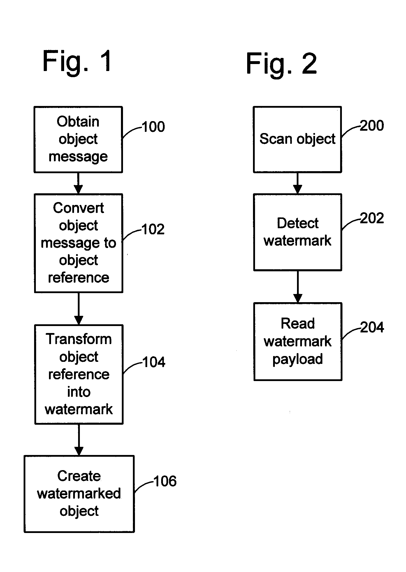
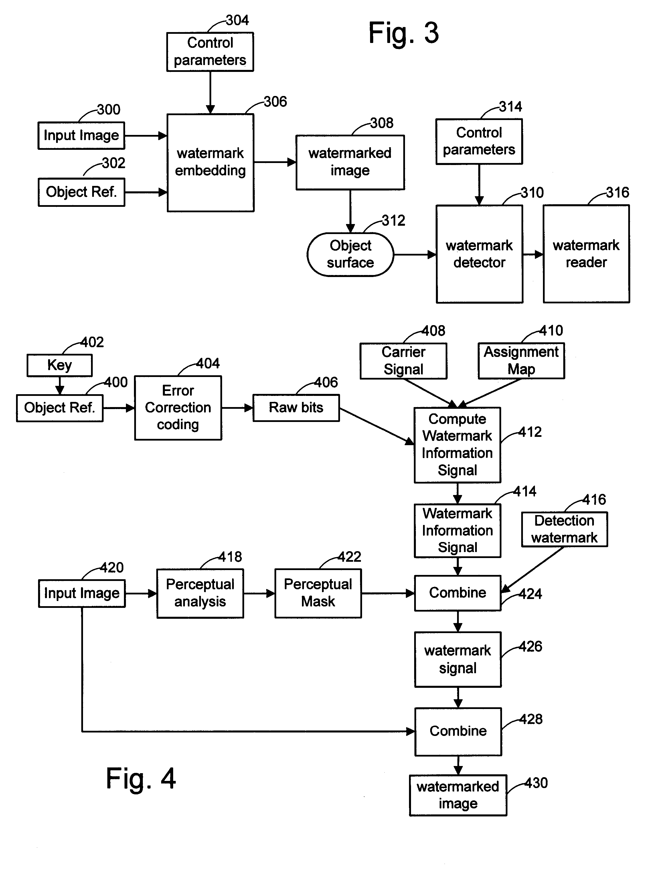
[0039] The following sections describe implementations of a watermark embedder and reader that operate on digital images. The embedder encodes the object reference into a digital image by modifying its image sample values such that the object reference is imperceptible to the ordinary observer in the output image. The embedder prints the output image on the surface of the object. To extract the object reference, the reader captures an image of the object and then processes it to detect the watermark and decode the object reference.

[0040]FIG. 3 is a block diagram summarizing image processing operations involved in embedding and reading a watermark. There are three primary inputs to the embedding process: the original, digitized image 300, the object reference 302, and a series of control parameters 304. The control parameters may include one or more keys. One key may be used to encrypt the object reference. Another key may be used to con...


PUM


Abstract

Watermarks and/or other related machine-readable coding techniques are used to provide data on or in objects. In one implementation a method includes providing an object with first machine-readable information. The first machine-readable information is provided on or in the object with a radio frequency identification (RFID) tag. The method also includes providing second machine-readable information on or in the object. The second machine-readable information is readable from optical scan data representing at least a portion of an object surface including the second-machine-readable information. The second machine-readable information is provided to cooperate with the first machine-readable information. Other implementations are provided as well.

Description

RELATED APPLICATION DATA [0001] This application is a continuation of U.S. patent application Ser. No. 09 / 452,021, filed Nov. 30, 1999 (now U.S. Pat. No. 7,044,395). The Ser. No. 09 / 452,021 application is a continuation-in-part of application Ser. No. 09 / 130,624, filed Aug. 6, 1998 (now U.S. Pat. No. 6,324,573), which is a continuation of application 08 / 508,083, filed Jul. 27, 1995 (now U.S. Pat. No. 5,841,978). [0002] The Ser. No. 09 / 452,021 application is also a continuation-in-part of each of application Ser. No.: 09 / 292,569, filed Apr. 15, 1999 (abandoned), Ser. No. 09 / 314,648, filed May 19, 1999, and Ser. No. 09 / 343,104, filed Jun. 29, 1999. [0003] The Ser. No. 09 / 452,021 application also claims the benefit of U.S. Provisional Application Nos.: 60 / 158,015, filed Oct. 6, 1999, 60 / 163,332, filed Nov. 3, 1999, and 60 / 164,619, filed Nov. 10, 1999. [0004] This application is related to applications Ser. No. 09 / 452,023, filed Nov. 30, 1999 (now U.S. Pat. No. 6,408,082) and Ser. No. 0...

Claims


Application Information

Patent Timeline
Patent Type & Authority Applications(United States)
IPC IPC(8): G06K7/10G06K19/06
CPCG06K19/086G07D7/0093G07D7/20G07D7/004G07D7/01
Inventor DAVIS, BRUCE L.RHOADS, GEOFFREY B.
Owner DIGIMARC CORP
Why Eureka
Try Eureka