Embedding and reading imperceptible codes on objects

a technology of imperceptible codes and objects, applied in the field of embedding and reading imperceptible codes on objects, can solve the problems of code not being aesthetically pleasing, occupying a dedicated portion of the physical object in which they reside, and needing to locate the code on a dedicated portion of the obj

Inactive Publication Date: 2006-05-16
DIGIMARC CORP
View PDF297 Cites 236 Cited by
  • Summary
  • Abstract
  • Description
  • Claims
  • Application Information

AI Technical Summary

Benefits of technology

[0005]While these forms of machine-readable identification are widely used and effective for many applications, they all have the disadvantage that they must occupy a dedicated portion of the physical object that they reside on. For example, if one wishes to apply a barcode or magnetic stripe to an object, the physical implementation of the code must occupy some portion of the object's surface apart from the other information content on the object. For some applications, this limitation does not pose a problem. For many applications, however, the need to locate the code on a dedicated portion of the object is a significant drawback. One drawback is that it requires the user to position the object so that the portion carrying the code can be read. Another drawback is that the code is not aesthetically pleasing, and may detract from the overall appearance of the object. In addition, the placement of the code may require an expensive and cumbersome manufacturing and application process.
[0006]Another characteristic of these forms of machine-readable identification is that they are perceptible to the users of the object. Again, for many applications, this characteristic is not a concern, and may in fact be a benefit. In some cases, however, it is a disadvantage for the code to be visually perceptible. As noted above, one drawback is that it detracts from the aesthetic appearance of the object. Another drawback is that it may be more likely to be tampered with.

Problems solved by technology

While these forms of machine-readable identification are widely used and effective for many applications, they all have the disadvantage that they must occupy a dedicated portion of the physical object that they reside on.
For many applications, however, the need to locate the code on a dedicated portion of the object is a significant drawback.
One drawback is that it requires the user to position the object so that the portion carrying the code can be read.
Another drawback is that the code is not aesthetically pleasing, and may detract from the overall appearance of the object.
In addition, the placement of the code may require an expensive and cumbersome manufacturing and application process.
In some cases, however, it is a disadvantage for the code to be visually perceptible.
As noted above, one drawback is that it detracts from the aesthetic appearance of the object.
Another drawback is that it may be more likely to be tampered with.

Method used


Image

  • Embedding and reading imperceptible codes on objects
  • Embedding and reading imperceptible codes on objects
  • Embedding and reading imperceptible codes on objects

Examples


example implementations

of Digital Image Watermark Embedder and Reader

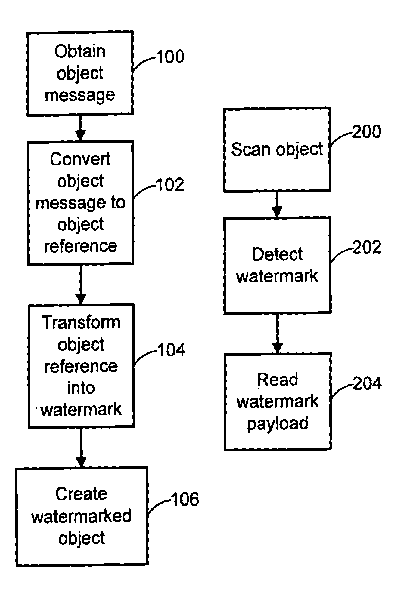
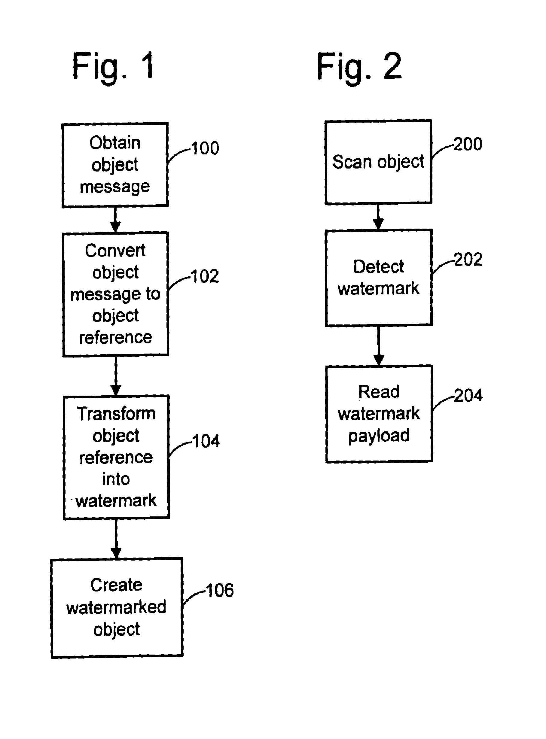
[0037]The following sections describe implementations of a watermark embedder and reader that operate on digital images. The embedder encodes the object reference into a digital image by modifying its image sample values such that the object reference is imperceptible to the ordinary observer in the output image. The embedder prints the output image on the surface of the object. To extract the object reference, the reader captures an image of the object and then processes it to detect the watermark and decode the object reference.

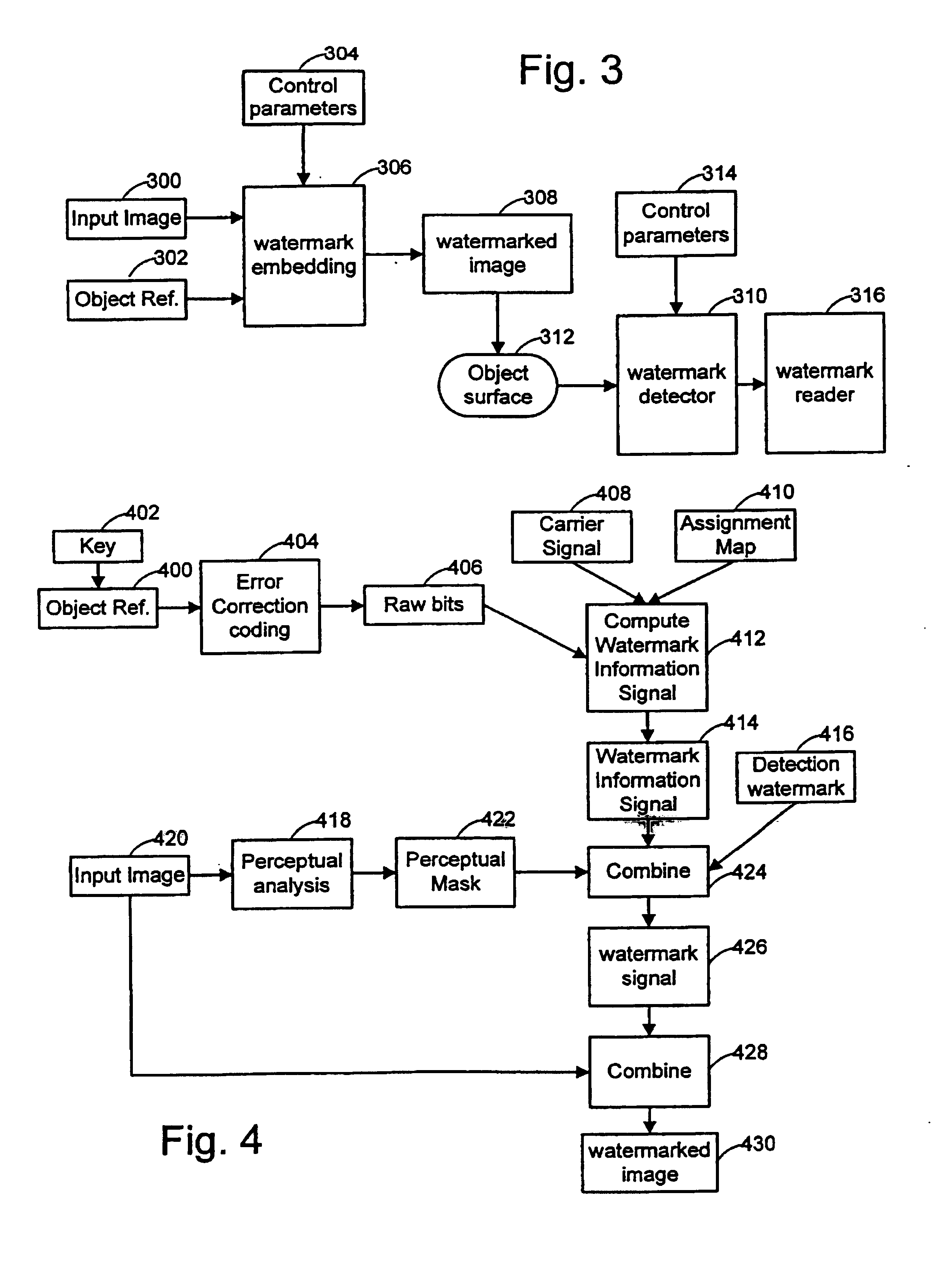
[0038]FIG. 3 is a block diagram summarizing image processing operations involved in embedding and reading a watermark. There are three primary inputs to the embedding process: the original, digitized image 300, the object reference 302, and a series of control parameters 304. The control parameters may include one or more keys. One key may be used to encrypt the object reference. Another key may be used to contr...


PUM


Abstract

Watermarks and related machine-readable coding techniques are used to embed data within the information content on object surfaces. These techniques may be used as a substitute for (or in combination with) standard machine-readable coding methods such as bar codes, magnetic stripes, etc. As such, the coding techniques extend to many applications, such as linking objects with network resources, retail point of sale applications, object tracking and counting, production control, object sorting, etc. Object message data, including information about the object, machine instructions, or an index, may be hidden in the surface media of the object. An object messaging system includes an embedder and reader. The embedder converts an object message to an object reference, and encodes this reference in a watermarked signal applied to the object. The reader detects the presence of a watermark and decodes the watermark signal to extract the object reference.

Description

RELATED APPLICATION DATA[0001]This application is a continuation-in-part of application Ser. No. 09 / 130,624, filed Aug. 6, 1998, (now U.S. Pat. No. 6,324,573), which is a continuation of application Ser. No. 08 / 508,083, filed Jul. 27, 1995, (now U.S. Pat. No. 5,841,978), which is a continuation in part of PCT application Ser. No. PCT / US94 / 13366, (published as WO 95 / 14289), filed Nov. 16, 1994, application Ser. No. 08 / 436,098, filed May 8, 1995, (now U.S. Pat. No. 5,636,292), application Ser. No. 08 / 436,099, filed May 8, 1995, (now U.S. Pat. No. 5,710,834), application Ser. No. 08 / 436,134, filed May 8, 1995, (now U.S. Pat. No. 5,748,763), application Ser. No. 08 / 438,159, filed May 8, 1995, (now U.S. Pat. No. 5,850,481), application Ser. No. 08 / 215,289, filed Mar. 17, 1994, (abandoned Mar. 15, 1996), and application Ser. No. 08 / 327,426, filed Oct. 21, 1994, (now U.S. Pat. No. 5,768,426), which is a continuation-in-part of application Ser. No. 08 / 154,866, filed Nov. 18, 1993, (abandone...

Claims


Application Information

Patent Timeline
Patent Type & Authority Patents(United States)
IPC IPC(8): G06K19/06
CPCG06T1/0064G06T2201/0052G06T2201/0051
Inventor DAVIS, BRUCE L.RHOADS, GEOFFREY B.
Owner DIGIMARC CORP
Why Eureka
Try Eureka