Fluorescent light air freshener

Inactive Publication Date: 2007-05-17
LOGAN MICHAEL A
View PDF6 Cites 5 Cited by
  • Summary
  • Abstract
  • Description
  • Claims
  • Application Information

AI Technical Summary

Problems solved by technology

Fluorescent bulbs, on the other hand, typically do not produce any significant amount of heat in the tube itself.
It is therefore not been considered a useful heating element.

Method used


Image

  • Fluorescent light air freshener
  • Fluorescent light air freshener
  • Fluorescent light air freshener

Examples


Embodiment Construction

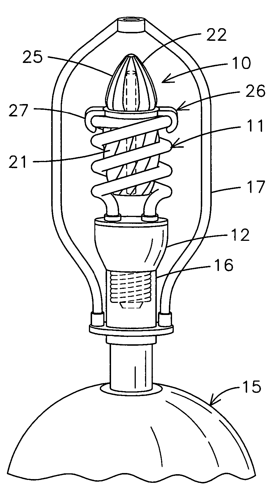
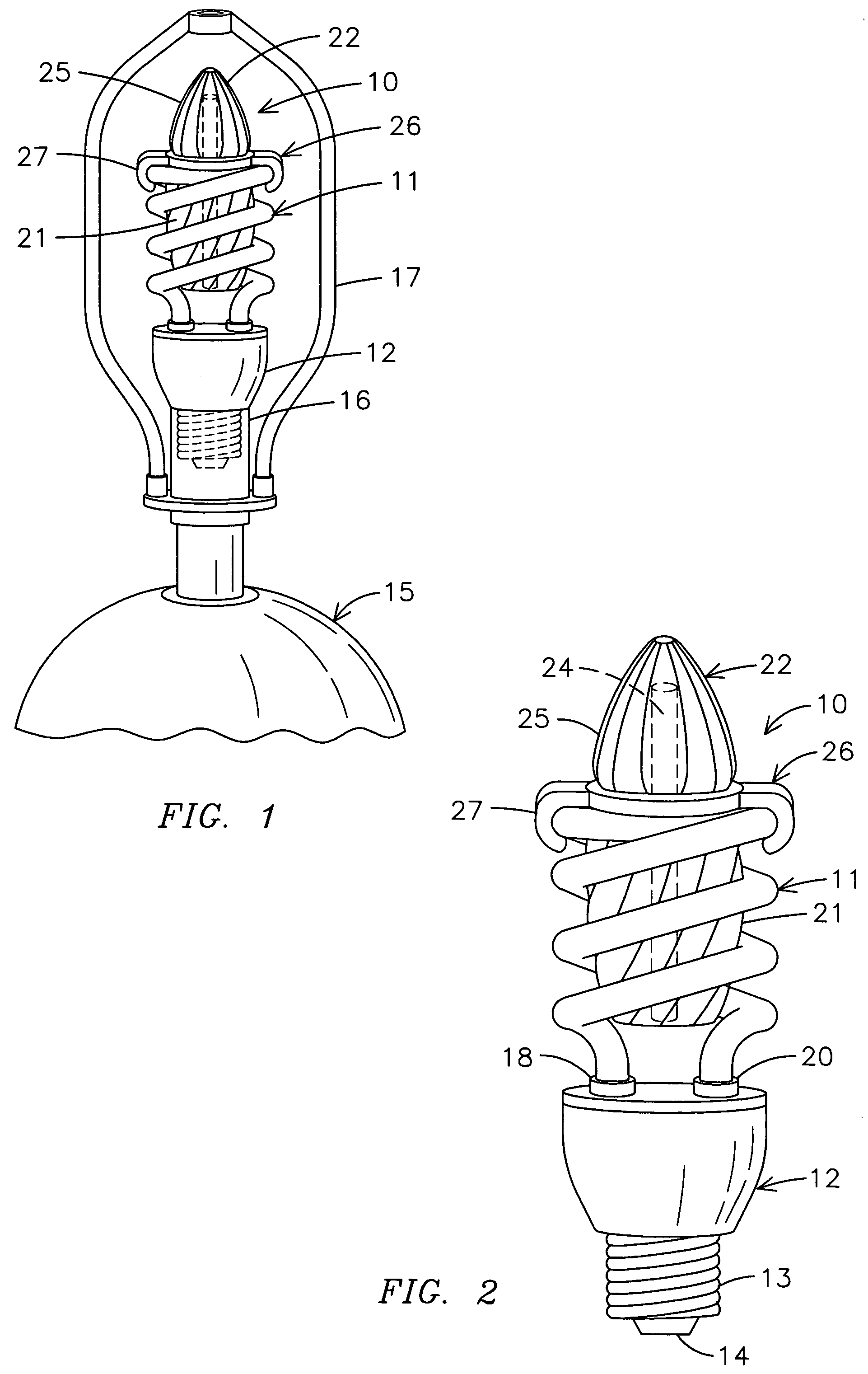
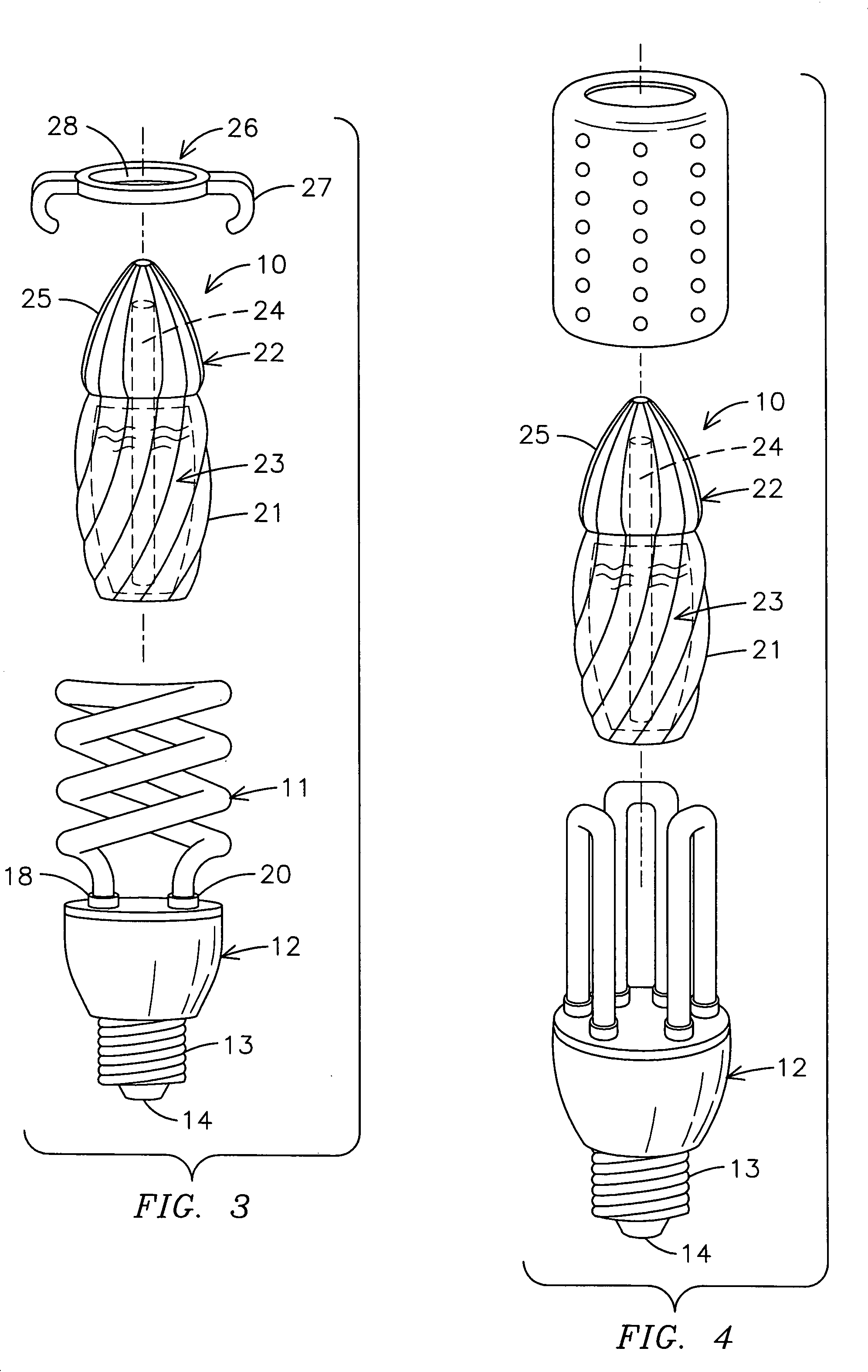
[0011] Referring to the drawings, FIGS. 1, 2 and 3, a fluorescent light air freshener dispenser 10 is illustrated attached to a coiled fluorescent tube 11 extending from an electronic ballast base 12. The ballast 12 can be seen as having a threaded base 13 with a center contact 14 similar to that found on incandescent light bulbs. The fluorescent light is designed for attachment to a lamp 15 having an incandescent lamp socket 16 with internal threads to which the threaded base 13 of the fluorescent tube ballast 12 can be threaded. The lamp 15 also has a lamp shade support 17 attached to the lamp stand 15. The coiled fluorescent tube 11 can be seen having two ends 18 and 20, each of which will have an electrode mounted at the end thereof. A permeable container 10 can be shown as having a base 21 and a permeable lid 22. The base 21 can be transparent and can have a reservoir 23 therein which may hold a liquid or solid or any other evaporative scent or air freshener.

[0012] As illustra...


PUM


Abstract

A fluorescent light air freshener dispenser has a fluorescent lamp having a coiled fluorescent tube attached to an electronic ballast. A permeable container is sized to fit in the coiled fluorescent tube and has a reservoir for holding an evaporative scent composition therein. A container supporting clip is attached to the permeable container and supports the permeable container in the center of the coiled fluorescent tube so that a fluorescent lamp dispenses the evaporative air freshener when the fluorescent lamp is activated.

Description

BACKGROUND OF THE INVENTION [0001] The present invention relates to room air fresheners and especially to room air fresheners that are placed in and attached to a coiled fluorescent tube of a fluorescent light. [0002] In the past, there have been a wide variety of room air fresheners and most of these typically use some type of heater for heating an evaporative air freshener composition or utilize some existing air flow, such as produced by a small fan or the like. One source for obtaining heat for a room air freshener can be from an incandescent lightbulb which operates by the passage of an electric current through a filament to produce a white hot filament producing the light for the lightbulb. Fluorescent bulbs, on the other hand, typically do not produce any significant amount of heat in the tube itself. A fluorescent lamp is a gas discharge tube in which the inner surface of the wall of the tube is coated with a light emitting or fluorescent substance. The tube is filled with a...

Claims


Application Information

Patent Timeline
IPC IPC(8): A61M16/00
CPCA61L9/037
Inventor LOGAN, MICHAEL A.
Owner LOGAN MICHAEL A
Why Eureka
Try Eureka