
Method of forming hydrophobic coating layer on surface of nozzle plate of inkjet printhead

Inactive Publication Date: 2007-05-31
SAMSUNG ELECTRO MECHANICS CO LTD
View PDF8 Cites 23 Cited by
  • Summary
  • Abstract
  • Description
  • Claims
  • Application Information

AI Technical Summary

Benefits of technology

[0017] The present general inventive concept provides a method of forming a hydrophobic coating layer on a surface of a nozzle plate of an inkjet printhead to improve ejection directionality and ejection uniformity of the inkjet printhead and to increase an ejection frequency.

Problems solved by technology

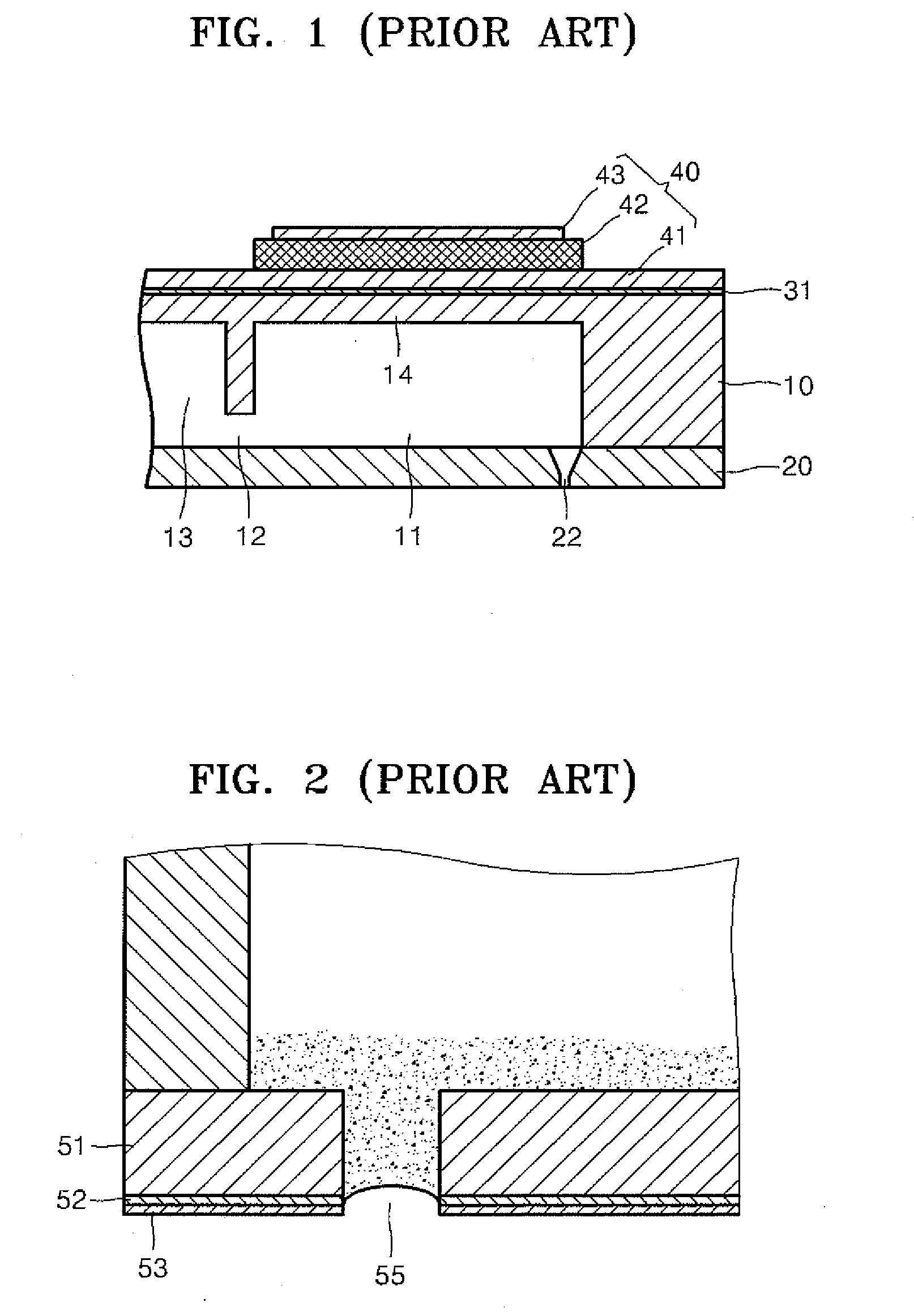
When the sulphur compound layer 53, which is a hydrophobic coating layer, is not properly formed, areas around each of the nozzles 55 are easily contaminated by ink and an ejection speed of an ink droplet is reduced or an ejection direction of an ink droplet becomes non-uniform, so that an ejection performance is impaired.
However, since nickel is reactive with a portion of ink, nickel is undesirable for commercial use.
However, this method requires a complicated apparatus and a difficult process, and thus it is difficult and expensive to use this method.

Method used


Image

  • Method of forming hydrophobic coating layer on surface of nozzle plate of inkjet printhead
  • Method of forming hydrophobic coating layer on surface of nozzle plate of inkjet printhead
  • Method of forming hydrophobic coating layer on surface of nozzle plate of inkjet printhead

Examples


Embodiment Construction

[0041] Reference will now be made in detail to the embodiments of the present general inventive concept, examples of which are illustrated in the accompanying drawings, wherein like reference numerals refer to the like elements throughout. The embodiments are described below in order to explain the present general inventive concept by referring to the figures. In the drawings, thicknesses of layers and regions may be exaggerated for clarity. A method of forming a hydrophobic coating layer on a surface of a nozzle plate, according to embodiments of the present general inventive concept, may be used on a thermal-driven type inkjet printhead as well as a piezoelectric inkjet printhead.

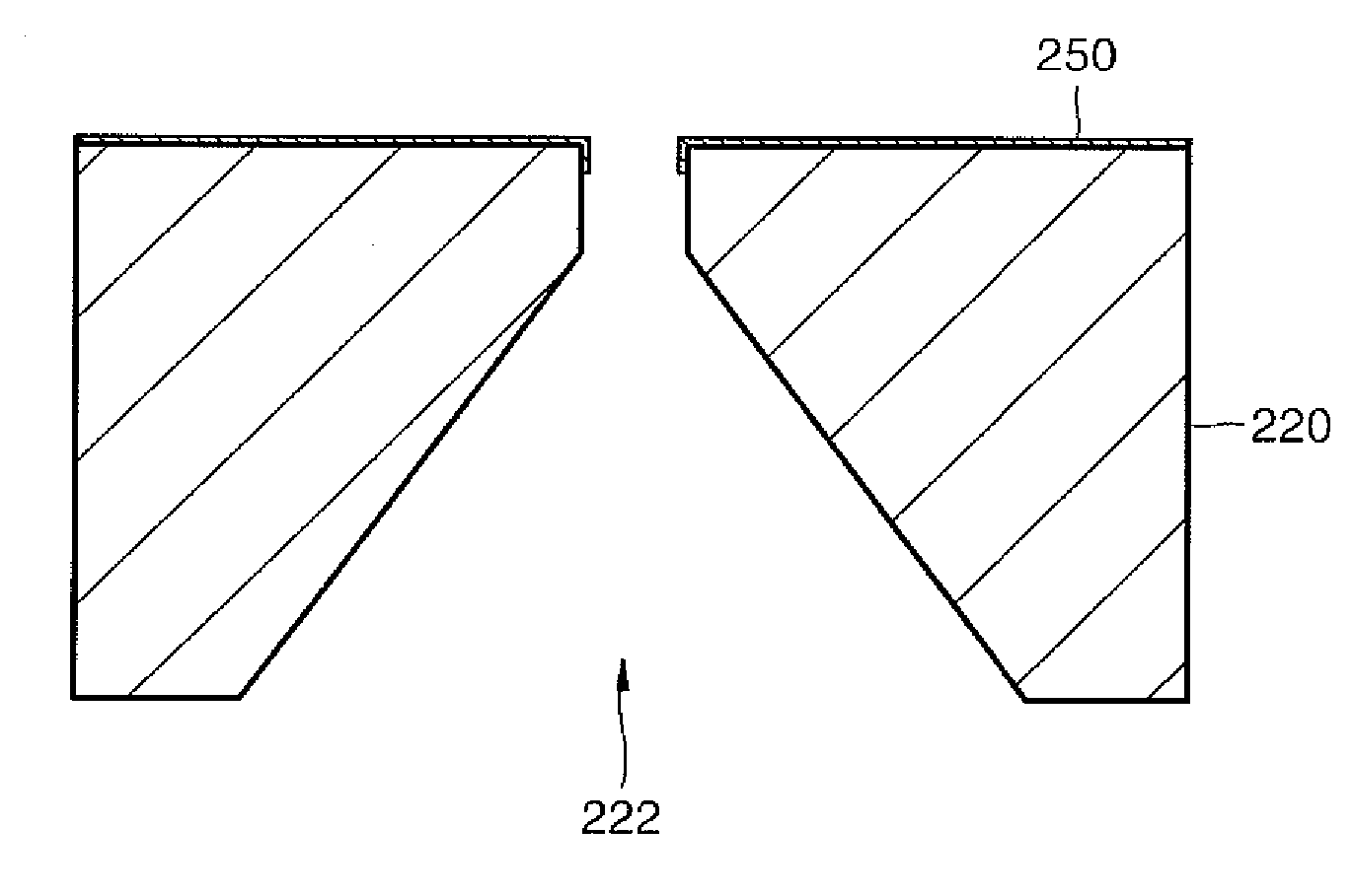
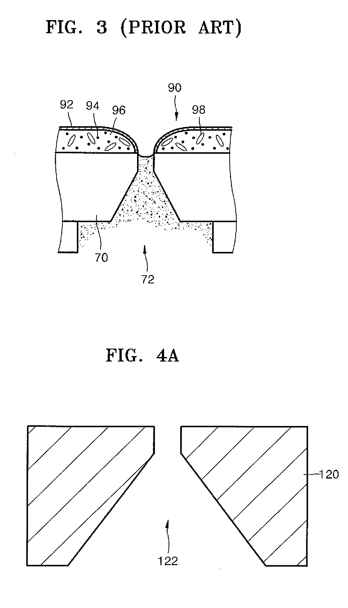
[0042]FIGS. 4A through 4H are views illustrating a method of forming a hydrophobic coating layer on a surface of a nozzle plate 120 of an inkjet printhead, according to an embodiment of the present general inventive concept. In the drawings, a partial portion of the nozzle plate 120 is illustrated with a...


PUM

PropertyMeasurementUnit
Depthaaaaaaaaaa
Thicknessaaaaaaaaaa
Depthaaaaaaaaaa

Abstract

A method of forming a hydrophobic coating layer on a surface of a nozzle plate of an inkjet printhead includes forming a plurality of nozzles in the nozzle plate, each of the nozzles having an exit, stacking a film on the surface of the nozzle plate to cover the exit of each of the nozzles, forming a predetermined metal layer on an inner wall of each of the nozzles and an inner surface of the film covering the exit of each of the nozzles using a plating method, removing the film from the surface of the nozzle plate, forming a hydrophobic coating layer on the surface of the nozzle plate to cover the metal layer exposed through the exit of each of the nozzles, and removing the metal layer formed on the inner wall of each of the nozzles and the hydrophobic coating layer formed on the surface of the metal layer.

Description

CROSS-REFERENCE TO RELATED APPLICATIONS [0001] This application claims priority under 35 U.S.C. §119(a) from Korean Patent Applications Nos. 10-2005-0113498, filed on Nov. 25, 2005, in the Korean Intellectual Property Office, and 10-2005-0124379, filed on Dec. 16, 2005, in the Korean Intellectual Property Office, the disclosures of which are incorporated herein by reference in their entireties. BACKGROUND OF THE INVENTION [0002] 1. Field of the Invention [0003] The present general inventive concept relates to an inkjet printhead having a hydrophobic layer, and more particularly, to a method of forming a hydrophobic coating layer on a surface of a nozzle plate of an inkjet printhead. [0004] 2. Description of the Related Art [0005] An inkjet printhead is a device that ejects fine ink droplets onto a desired position of a recording medium to print an image of a predetermined color. The inkjet printhead may be roughly classified into two types of printheads, depending on an ink ejecting...

Claims


Application Information

Patent Timeline
IPC IPC(8): B41J2/135
CPCB41J2/1433B41J2/1606B41J2/162Y10T29/49401B41J2/1631B41J2/1643B41J2/1628
Inventor KANG, SUNG-GYUBACK, KAE-DONGLIM, SEUNG-MOCHUNG, JAE-WOO
Owner SAMSUNG ELECTRO MECHANICS CO LTD
Learn More