Electric signal outputting apparatus, semiconductor laser modulation driving apparatus, and image forming apparatus

Inactive Publication Date: 2007-06-07
RICOH KK
View PDF9 Cites 9 Cited by
  • Summary
  • Abstract
  • Description
  • Claims
  • Application Information

AI Technical Summary

Benefits of technology

[0008] The present invention may provide an electric signal outputting apparatus, a semiconductor laser modulation driving apparatus, and an

Problems solved by technology

However, in a case where the output impedance of the output side does not match the impedance of the transmission line (more specifically, in a case where the input impedance of the receiver side does not match the characteristic impedance of the transmission line), the waveform of the output signals may become distorted by reflection caused when increasing the speed of the frequency components included in the output signals.
Such distortion in the waveform of the signals may adversely affect data transmission.
However, even in a case where a match in the impedances is obtained, the increase in the speed of the o

Method used


Image

  • Electric signal outputting apparatus, semiconductor laser modulation driving apparatus, and image forming apparatus
  • Electric signal outputting apparatus, semiconductor laser modulation driving apparatus, and image forming apparatus
  • Electric signal outputting apparatus, semiconductor laser modulation driving apparatus, and image forming apparatus

Examples


first example

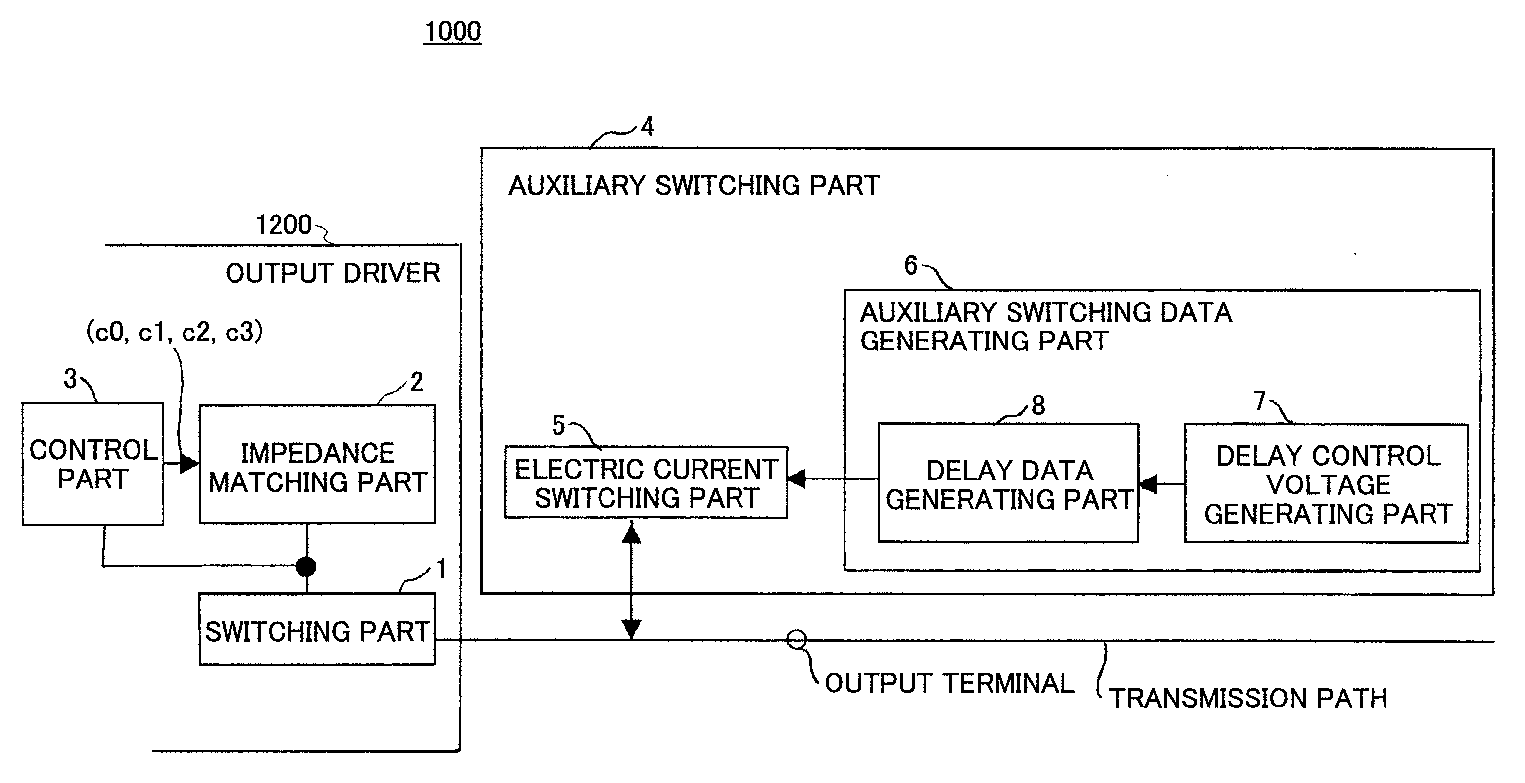
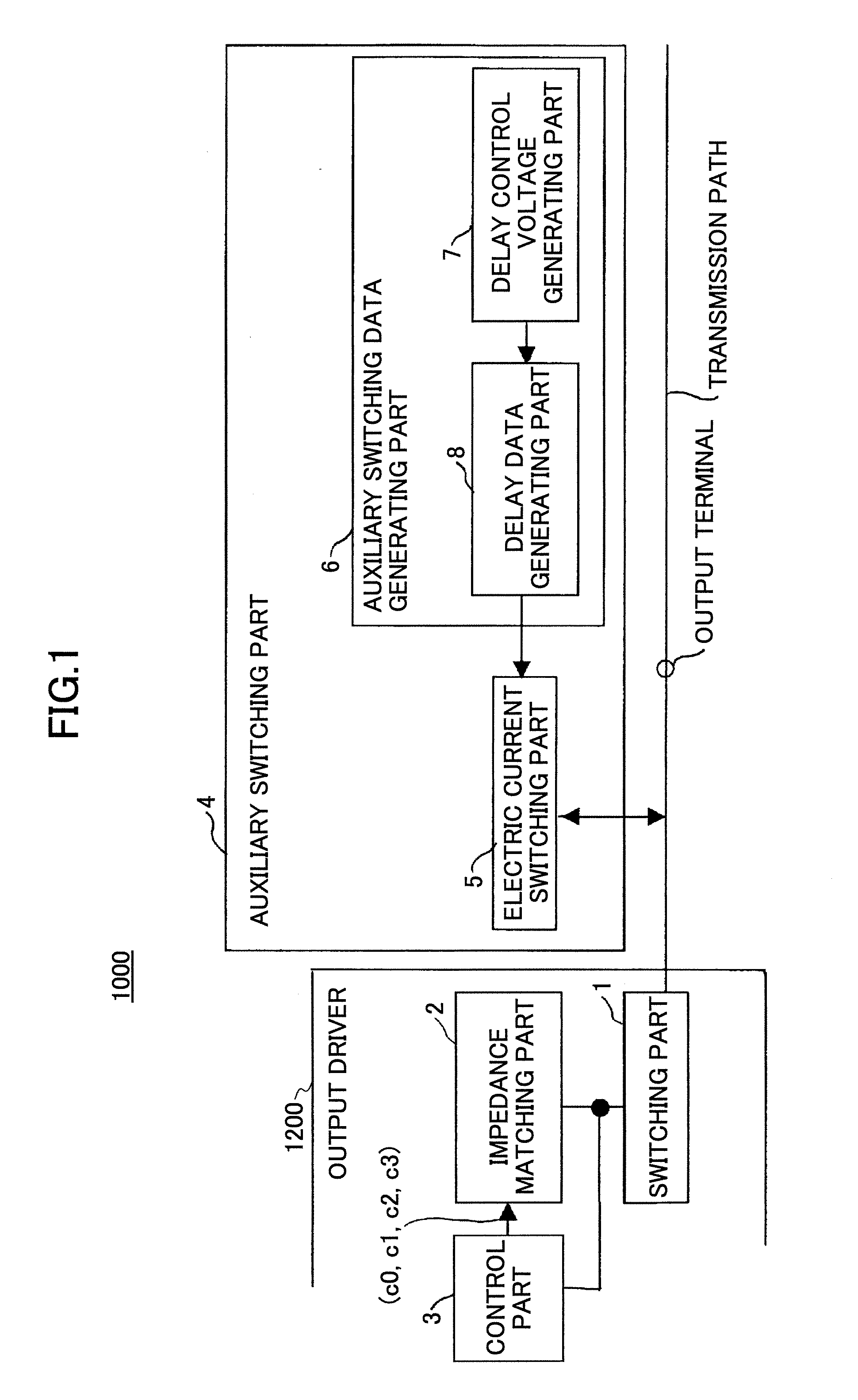
[0066]FIG. 1 shows an exemplary configuration of an electric signal outputting apparatus 1200 in a serial electric transmission system 1000 according to an embodiment of the present invention. The electric signal outputting apparatus 1200 according to this embodiment of the present invention is used for a serial electric transmission system 1000 and includes a switching part 1 for switchably generating high and low output signals in accordance with signal data and transmitting the output signals to a transmission path (output node) connected to, for example, the serial electric transmission system 1000, an impedance matching part 2 for matching the impedance of the electric signal outputting apparatus (output impedance) 1200 to the impedance of the transmission path, a control part (controller) for setting the impedance matching part 2 for enabling the impedance matching part 2 to match the output impedance of the electric signal outputting apparatus 1200 to the impedance of the tra...

second example

[0111]FIG. 21 shows an exemplary configuration of an electric signal outputting apparatus 2200 in a serial electric transmission system 2000 according to an embodiment of the present invention. The electric signal outputting apparatus 2200 according to this embodiment of the present invention is used for a serial electric transmission system 2000 and includes a switching part 1 for switchably generating high and low output signals in accordance with signal data and transmitting the output signals to a transmission path (output node) connected to, for example, a serial electric transmission system 2000, an impedance matching part 2 for matching an output impedance to the impedance of the transmission path, the impedance matching part including a reference voltage generating part and a terminal part controlled in accordance with a voltage generated by the reference voltage generating part, and an auxiliary switching part for subsidiarily supplying current to an output node in the tran...


PUM


Abstract

The present invention discloses an electric signal outputting apparatus in a serial electric transmission system. The electric signal outputting apparatus includes a switching part for switchably generating high and low output signals in accordance with signal data and transmitting the output signals to a transmission path, an impedance matching part for matching an output impedance to the impedance of the transmission path, and an auxiliary switching part for subsidiarily supplying current to an output node in the transmission path and subsidiarily absorbing current from the output node in the transmission path when the switching part switches the generation between high and low output signals, wherein the auxiliary switching part conducts the supplying and the absorbing for a period shorter than a pulse width of a reference clock of the serial electric transmission system.

Description

BACKGROUND OF THE INVENTION [0001] 1. Field of the Invention [0002] The present invention relates to an electric signal outputting apparatus, a semiconductor laser modulation driving apparatus, and an image forming apparatus. [0003] 2. Description of the Related Art [0004] In recent years and continuing, the band of signals output (output signal band) from an electric signal outputting apparatus (e.g. output driver of an integrated circuit) has drastically increased to a high speed along with, for example, the forming of fine-sized integrated circuits and the use of serial signal transmission methods. As the speed of the output signal bands increases, the electric signal outputting apparatus (e.g. output driver) is expected to fulfill more requirements. [0005] For example, since it becomes difficult to accurately transfer data when the rise or drop of a signal wave is slow or when the jitter of a reference clock is large, it is desired for the electric signal outputting apparatus (e...

Claims


Application Information

Patent Timeline
IPC IPC(8): H03K3/08
CPCH03K19/0005
Inventor OZASA, DAN
Owner RICOH KK
Why Eureka
Try Eureka