Transformer and method of assembly

a transformer and transformer technology, applied in the field of transformers, can solve the problems of increasing the cost of assembling transformers, increasing the cost of manufacturing transformers, increasing the cost and/or the time of manufacturing transformers, etc., and achieve the effect of facilitating electrical coupling of conductor windings

Inactive Publication Date: 2007-06-14
GENERAL ELECTRIC CO
View PDF10 Cites 13 Cited by
  • Summary
  • Abstract
  • Description
  • Claims
  • Application Information

AI Technical Summary

Benefits of technology

[0007] In another aspect, a method is provided for assembling a transformer including a terminal and a coil having a conductor winding. The method includes providing a first opening within an end of the conductor winding, providing a second opening within the terminal of the transformer, and fixedly securing the conductor winding end to the terminal by receiving a fastener within the first and second openings to facilitate electrically coupling the conductor winding to the terminal.
[0008] In another aspect, a method is provided for assembling a transformer including a terminal and a coil having a conductor winding. The method includes providing a clamp, and fixedly securing the conductor winding to the terminal using the clamp to facilitate electrically coupling the conductor winding to the terminal.

Problems solved by technology

However, welding the coil winding ends to the terminals may require welding equipment, welding supplies, and / or operator training, which may increase a cost of assembling the transformer.
However, because transformers and their components may have a variety of sizes and shapes, at least some known transformers may require different sized and / or shaped terminal board assemblies, which may increase a cost of manufacturing transformers.
Moreover, some known terminal board assemblies may be machined to fit the transformer, which may increase a cost and / or a time of manufacturing transformers.

Method used


Image

  • Transformer and method of assembly
  • Transformer and method of assembly
  • Transformer and method of assembly

Examples


Embodiment Construction

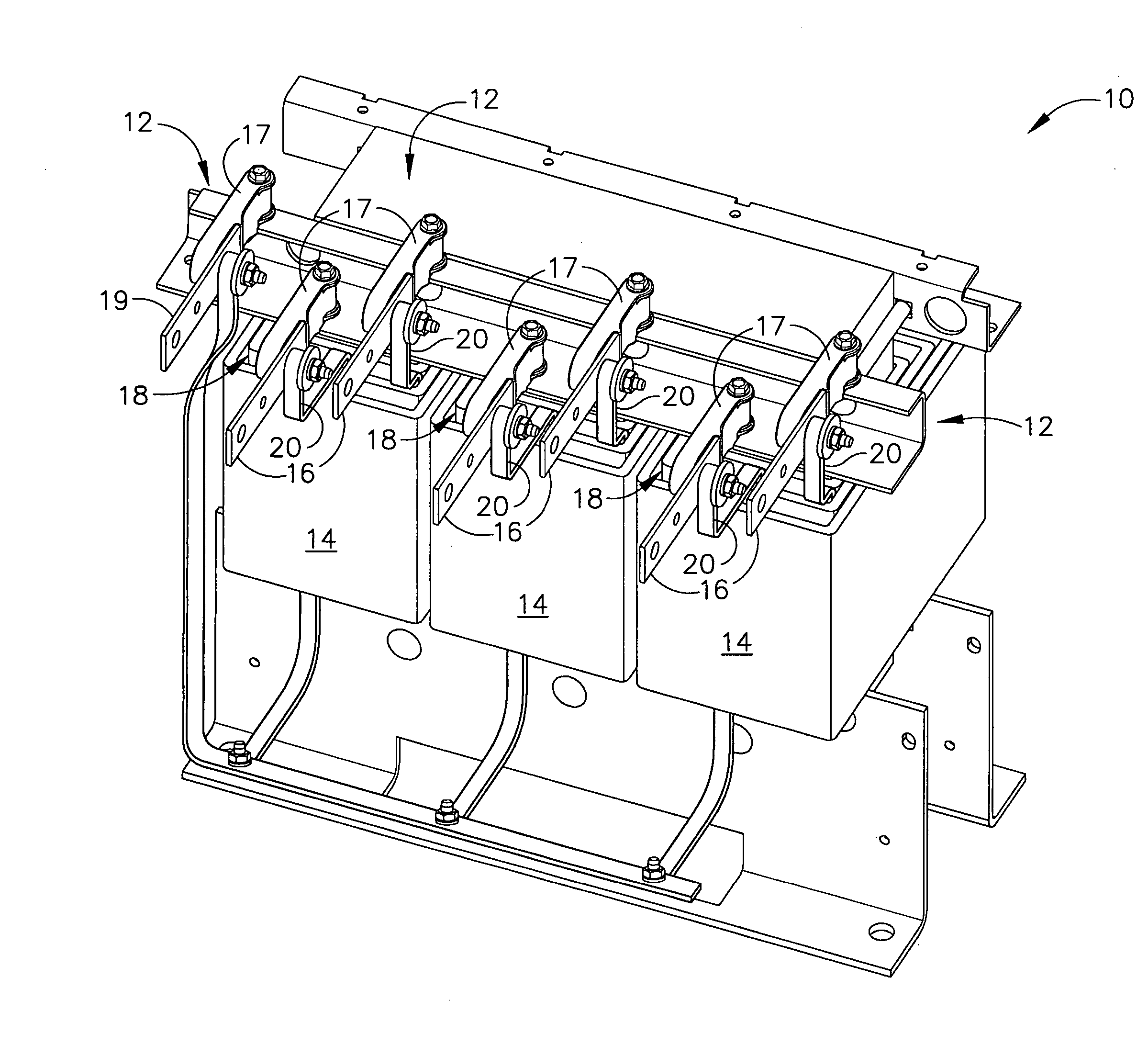
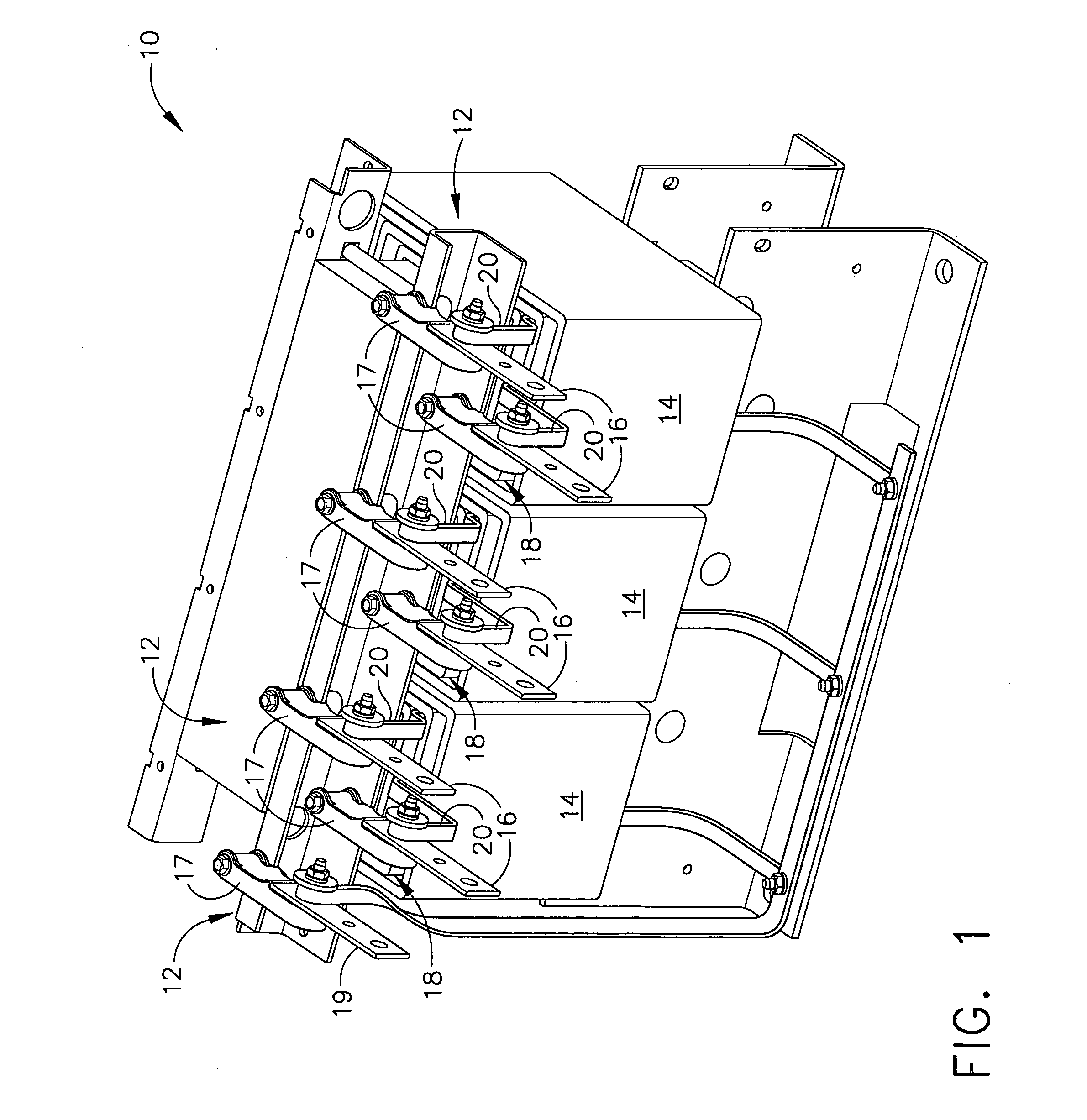
[0016]FIG. 1 is a perspective view of an exemplary embodiment of a transformer 10. Transformer 10 generally includes a frame 12, a plurality of coils 14 coupled to frame 12, and a plurality of terminals 16 coupled to frame 12 via a plurality of corresponding, and independent, insulators 17. Transformer 10 may be any type of transformer. For example, in the exemplary embodiment transformer 10 is a medium power dry-type transformer, however transformer 10 may be another type of transformer. Coils 14 each include two or more windings 18 of a conductor 20 that are each wound around a core (not shown) for transferring electrical energy therebetween. Although in the exemplary embodiment each winding 18 is formed from only one conductor, each winding may include any number of conductor(s). Each coil 14 may be any type of coil, for example including any number of conductor windings 18, any number of turns of each conductor winding 18, any size, shape, and / or material of each conductor 20 fo...


PUM

PropertyMeasurementUnit
electricallyaaaaaaaaaa
pressureaaaaaaaaaa
timeaaaaaaaaaa

Abstract

A transformer includes a frame and a coil comprising a conductor winding. The conductor winding includes an end having a first opening. The transformer also includes a terminal coupled to the frame. The terminal includes a second opening. A fastener is received within the first and second openings. The fastener fixedly secures said conductor winding end to said terminal to electrically couple said conductor winding to said terminal.

Description

BACKGROUND OF THE INVENTION [0001] This invention relates generally to electrical transformers, and more specifically to methods for assembling electrical transformers. [0002] At least some known electrical transformers include one or more coils mounted on a base, or frame. Each coil includes two or more conductor windings. Some known transformers include a plurality of terminals for circuit connections. The terminals are connected to the ends of the coil windings. More specifically, in at least some known transformers, for example medium power dry-type transformers, the coil windings ends are welded to the terminals. However, welding the coil winding ends to the terminals may require welding equipment, welding supplies, and / or operator training, which may increase a cost of assembling the transformer. Moreover, the welding process may increase at time of assembling the transformer. [0003] In at least some known transformers, the terminals are mounted on a terminal board assembly th...

Claims


Application Information

Patent Timeline
Patent Type & Authority Applications(United States)
IPC IPC(8): H01F27/26
CPCH01F27/2828H01F27/29Y10T29/4902H01F30/12Y10T29/49007H01F27/306
Inventor OSBUN, KEVIN P.
Owner GENERAL ELECTRIC CO
Why Eureka
Try Eureka