Birefringence-compensated liquid crystal display and projection system using same

a liquid crystal display and projection system technology, applied in television systems, instruments, non-linear optics, etc., can solve the problems of increasing the cost of producing a projection system, the careful alignment required to achieve the optimum orientation of the quarter wave retarder, etc., to achieve the effect of maximizing the contrast of image ligh

Inactive Publication Date: 2007-06-14
3M INNOVATIVE PROPERTIES CO
View PDF11 Cites 2 Cited by
  • Summary
  • Abstract
  • Description
  • Claims
  • Application Information

AI Technical Summary

Benefits of technology

[0007] One embodiment of the invention is directed to a projection system that includes a first image-forming device and a first polarizing beamsplitter. Illumination light passes via the first polarizing beamsplifter to the first image-forming device. A first retardation element is disposed between the first image-forming device and the first polarizing beamsplitter. A bias controller is attached to the first image-forming device and applies a bias to pixels in the dark state so as to substantially maximize contrast in image light that has passed through the first polarizing beamsplitter from the first image-forming device.

Problems solved by technology

One disadvantage of this compensation technique, however, is the very careful alignment required to achieve the optimum orientation of the quarter wave retarder.
This alignment step increases the costs of producing a projection system.

Method used


Image

  • Birefringence-compensated liquid crystal display and projection system using same
  • Birefringence-compensated liquid crystal display and projection system using same
  • Birefringence-compensated liquid crystal display and projection system using same

Examples


example

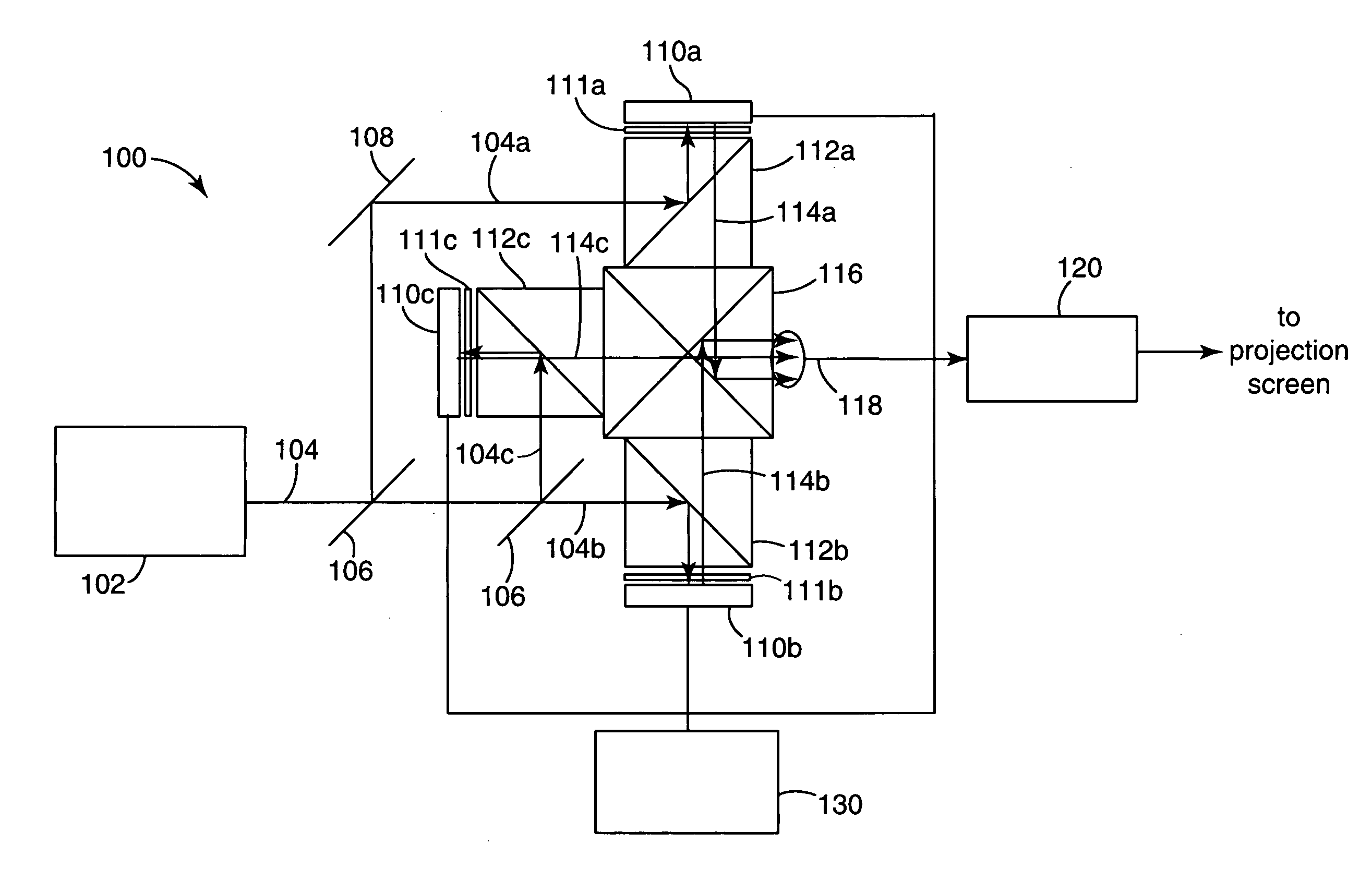
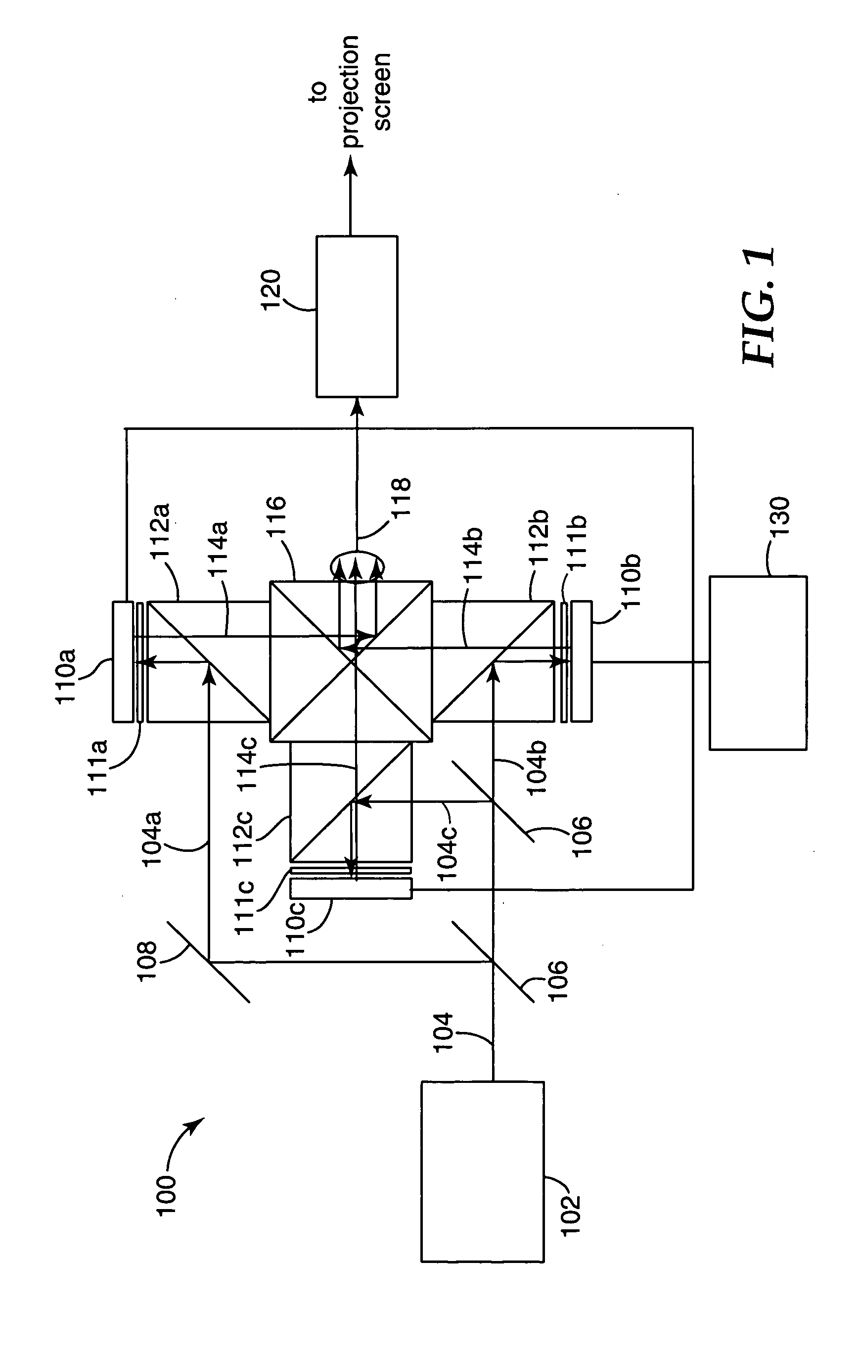
[0039] The technique was tested on a type 720p VAN mode liquid crystal on silicon (LCoS) image-forming device, supplied by Brillian Corp, Tempe, Ariz. A quarter-wave retarder on a precision rotation stage was positioned between a polarizing beamsplitter and the image-forming device. The system was illuminated with green light from an arc lamp at f / 2.3. The illumination light was reflected by the polarizing beamsplitter to the image-forming device. A projection lens was mounted to project the light reflected by the image-forming device that was transmitted by the polarizing beamsplitter. A light meter was placed 10 cm in front of the projection lens to measure the projected light flux. The angle of rotation of the quarter-wave retarder required to compensate this imager optimally is around 0.25°, corresponding to a residual birefringence of approximately 0.75 nm.

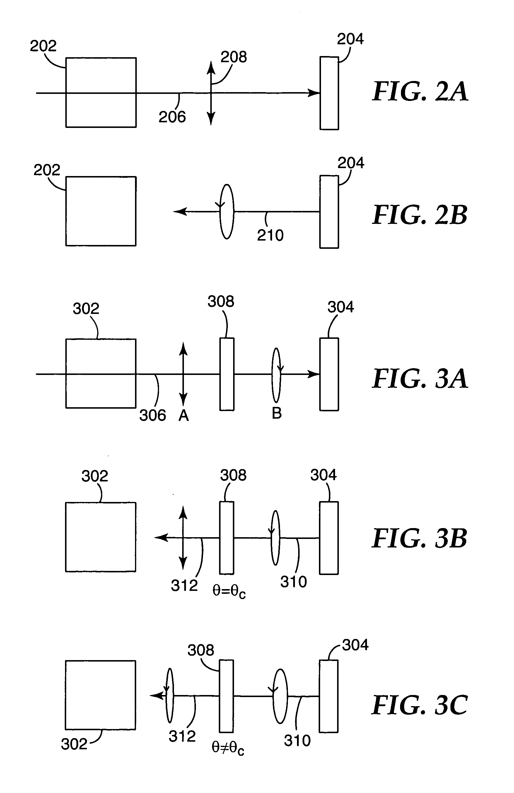
[0040] The retarder was aligned so that an optimally dim dark state was achieved with the image-forming device set to a gr...


PUM


Abstract

A projection system includes an image-forming device and a polarizing beamsplitter. Illumination light illuminates the image-forming device via the first polarizing beamsplitter. A retardation element is disposed between the image-forming device and the polarizing beamsplitter. A bias controller applies a bias to pixels of the image-forming device in the dark state so as to substantially maximize contrast in image light reflected from image-forming device. In some arrangements, the volume between the polarizing beamsplitter and the image-forming device is sealed, with the retarding element being disposed within the sealed volume and being attached to either the polarizing beamsplitter or the image-forming device.

Description

FIELD OF THE INVENTION [0001] The present invention relates to image projection systems. More specifically, the invention relates to projection systems that use liquid crystal imaging panels for generating the image. BACKGROUND [0002] Many image projection systems, such as might be used for projection televisions, are based on the use of liquid crystal display (LCD) imager panels. Some LCD panels operate in a reflective mode, in which incident illumination light is separated from reflected image light by using a polarizing beamsplitter in front of the reflective LCD panel. In such configurations, the illumination light is passed to the LCD panel via the polarization beamsplitter. The illumination light incident at the LCD panel is, therefore, polarized. The LCD panel operates by selectively adjusting the polarization modulation of the many pixels of the panel. Those pixels associated with dark areas of the image do not alter the polarization state of the light whereas those pixels a...

Claims


Application Information

Patent Timeline
Patent Type & Authority Applications(United States)
IPC IPC(8): G02B27/14
CPCH04N5/7441H04N9/3167H04N9/3197H04N5/74
Inventor BRUZZONE, CHARLES L.AASTUEN, DAVID J.W.KEYES, MICHAEL P.
Owner 3M INNOVATIVE PROPERTIES CO
Why Eureka
Try Eureka