Laser scanning type observation apparatus having a delay circuit unit, a multi-stage delay setting unit and a decision unit

a technology of laser scanning and observation apparatus, applied in the direction of optical radiation measurement, photometry using electric radiation detector, instruments, etc., to achieve the effect of maximizing contrast, removing background noise, and improving image quality

Active Publication Date: 2016-05-24
EVIDENT CORP
View PDF13 Cites 2 Cited by
  • Summary
  • Abstract
  • Description
  • Claims
  • Application Information

AI Technical Summary

Benefits of technology

[0021]According to the present invention, it is possible to acquire a laser scanning type observation apparatus: capable of sampling detection signals at the optimum timing for forming images without complicated adjustment for various observation conditions; and, in addition, capable of improving image qualities by maximizing contrast between detection signals and by removing background noise.
[0022]Also, according to the present invention, it is possible to acquire a laser scanning microscope apparatus: capable of detecting detection signals with large intensities; and capable of improving image qualities, even when an AC-coupled amplifier is used for the laser scanning microscope apparatus.

Problems solved by technology

However, laser beams with various wavelengths have been used in recent years because of diversification of test objects for research, and laser beams are often generated also by causing pulse oscillation with a mode-locking method or the like.

Method used


Image

  • Laser scanning type observation apparatus having a delay circuit unit, a multi-stage delay setting unit and a decision unit
  • Laser scanning type observation apparatus having a delay circuit unit, a multi-stage delay setting unit and a decision unit
  • Laser scanning type observation apparatus having a delay circuit unit, a multi-stage delay setting unit and a decision unit

Examples


first embodiment

The First Embodiment

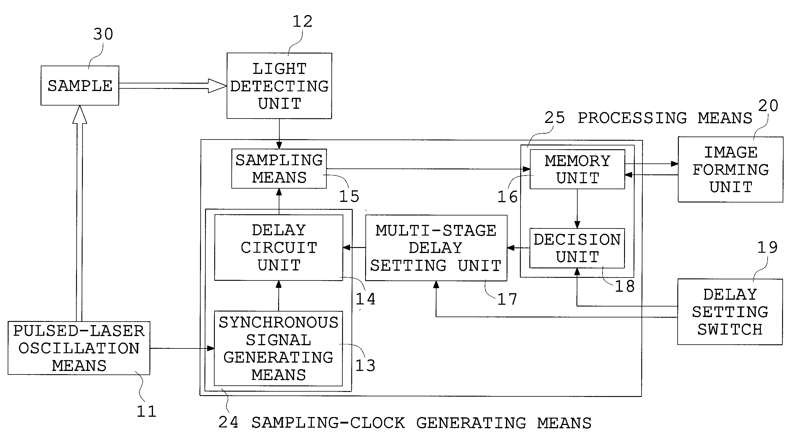
[0084]FIG. 5 is a block diagram schematically showing a structure of a laser scanning type observation apparatus of a first embodiment according to the present invention. FIG. 6 is an explanatory view showing one example of electrical signals outputted by a light detecting unit performing photoelectric conversion, one example of a synchronous signal synchronizing with an oscillation of pulsed laser, and one example of timing at which the synchronous signal is delayed, in the laser scanning type observation apparatus shown in FIG. 5. FIG. 7 is an explanatory view showing one example of timing charts of oscillation of pulsed laser, an electric signal into which light is photo-electrically converted by the light detecting unit and which is outputted by the light detecting unit, a synchronous signal synchronizing with the oscillation of the pulsed laser, and a trigger signal (sampling clock) that are outputted with a delay of a set amount of time relative to the sync...

second embodiment

The Second Embodiment

[0110]FIG. 9 is a block diagram schematically showing a structure of a laser scanning type observation apparatus according to a second embodiment of the present invention. FIG. 10 is an explanatory view showing one example of timing charts of oscillation of pulsed laser, an electric signal into which light is photo-electrically converted by the light detecting unit and which is outputted by the light detecting unit, a synchronous signal synchronizing with the oscillation of the pulsed laser, and a trigger signal (sampling clock) that is outputted with a delay of a set amount of time relative to the synchronous signal, in the laser scanning type observation apparatus shown in FIG. 9. Besides, components for the second embodiment which have the same structures as in FIG. 5 are given the same numeral references respectively, and detailed explanations about these components are omitted.

[0111]A laser scanning type observation apparatus according to the present embodi...

third embodiment

The Third Embodiment

[0132]FIG. 11 is a block diagram schematically showing a structure of a laser scanning type observation apparatus according to a third embodiment of the present invention. FIG. 12 is an explanatory view showing one example of a delay optical path unit provided for the laser scanning type observation apparatus shown in FIG. 11. FIGS. 13A to 13E are explanatory views showing a time delay of pulsed laser delayed by the delay optical path unit shown in FIG. 12 in the laser scanning type observation apparatus shown in FIG. 11, FIG. 13A is a view showing pulsed laser passing through a first optical path of the delay optical path unit, FIG. 13B is a view showing pulsed laser passing through a second optical path of the delay optical path unit to be delayed, FIG. 13C is a view showing pulsed laser passing through a third optical path of the delay optical path unit to be delayed, FIG. 13D is a view showing pulsed laser passing through a fourth optical path of the delay op...


PUM

PropertyMeasurementUnit
oscillation frequencyaaaaaaaaaa
frequencyaaaaaaaaaa

Abstract

A laser scanning type observation apparatus includes a pulsed-laser oscillation means irradiating pulsed laser to an object, a detector receiving light from the object to output a detection signal, a means detecting pulsed-laser oscillation to output a synchronous signal, a circuit delaying the synchronous signal for an optional amount of time to output a trigger signal, a means sampling the detection signal in synchronization with the trigger signal, a memory storing the sampled detection signal, a setting unit capable of setting delay time for delaying the synchronous signal in two or more stages within one period of the synchronous signal, and a decision unit determining an optimum delay stage for image formation using data on intensities of the detection signal at the respective delay stages, wherein the setting means fixes delay time for delaying the synchronous signal at delay time corresponding to the delay stage determined by the decision unit.

Description

[0001]This application claims benefits of Japanese Patent Applications No. 2012-030871 filed in Japan on Feb. 15, 2012, Japanese Patent Applications No. 2012-159912 filed in Japan on Jul. 18, 2012, Japanese Patent Applications No. 2012-159913 filed in Japan on Jul. 18, 2012, Japanese Patent Applications No. 2012-159914 filed in Japan on Jul. 18, 2012, and Japanese Patent Applications No. 2012-253378 filed in Japan on Nov. 19, 2012, the contents of which are hereby incorporated by this reference.BACKGROUND OF THE INVENTION[0002]1. Field of the Invention[0003]This invention relates to a laser scanning type observation apparatus, such as laser scanning microscope and laser scanning endoscope, in which a pulsed laser is irradiated to a test object and then detection signals acquired by receiving light from the test object are sampled.[0004]2. Description of Related Art[0005]In general, as shown in FIG. 1 for example, a laser scanning microscope is configured to include: a light source 5...

Claims


Application Information

Patent Timeline
Patent Type & Authority Patents(United States)
IPC IPC(8): G02B21/00G01N21/17G02B23/24G02B21/16G01J1/44G01J1/42
CPCG01N21/17G01J1/44G02B21/002G02B21/0084G02B21/16G02B23/24G01J2001/4242G01N2201/0697G01N2201/06113
Inventor FUJINUMA, KENTAKAHASHI, SHINTARO
Owner EVIDENT CORP
Why Eureka
Try Eureka