Panel assembly with trim plates

a panel assembly and trim plate technology, applied in the direction of transportation and packaging, building lifts, etc., can solve the problems of high force, heavy decoration panels and trim plates, and mounting of panels

Inactive Publication Date: 2007-08-09
BOSTOCK GLENN A
View PDF27 Cites 7 Cited by
  • Summary
  • Abstract
  • Description
  • Claims
  • Application Information

AI Technical Summary

Problems solved by technology

Decorative panels and the trim plates may be heavy and, therefore, require robust attachment to the supporting structure provided by the elevator cab.
Particularly high forces are induced during testing of the elevator, when interior panels and trim plates have been known to break free of their mountings and fall into the interior of the elevator cab.
Mounting of the panels is a challenge because the mounting must be robust while not compromising the decorative aspects of the elevator's interior design.
It is also preferable to mount the panels and trim plates from the interior of the cab because there is limited space between the cab and the elevator shaft which makes access to the mounting hardware difficult.

Method used


Image

  • Panel assembly with trim plates
  • Panel assembly with trim plates
  • Panel assembly with trim plates

Examples


Embodiment Construction

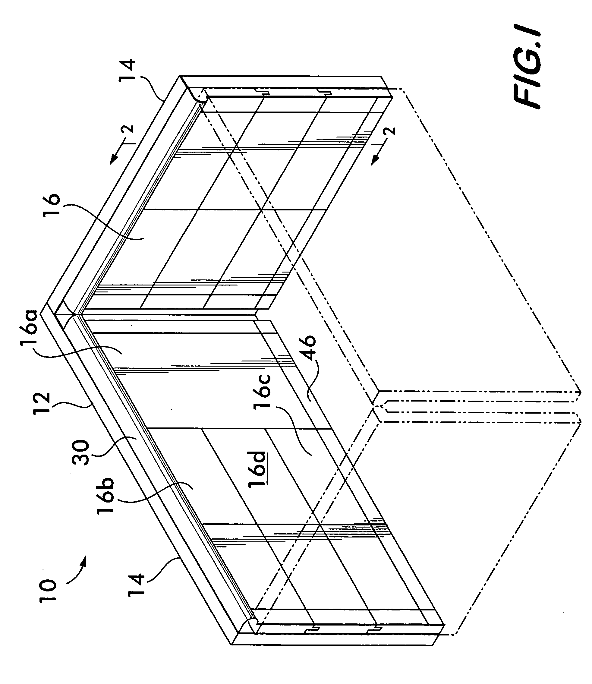
[0019]FIG. 1 shows a panel assembly 10 attached to a support structure 12, in this example, the interior of an elevator cab 14. It is understood that the panel assembly is not limited to use in elevator cabs, but may be attached to any structure wherein an aesthetically pleasing surface is desired. Elevator cab 14 is of course positionable within an elevator shaft of a building and is vertically movable within the shaft between floors of the building as is well understood.

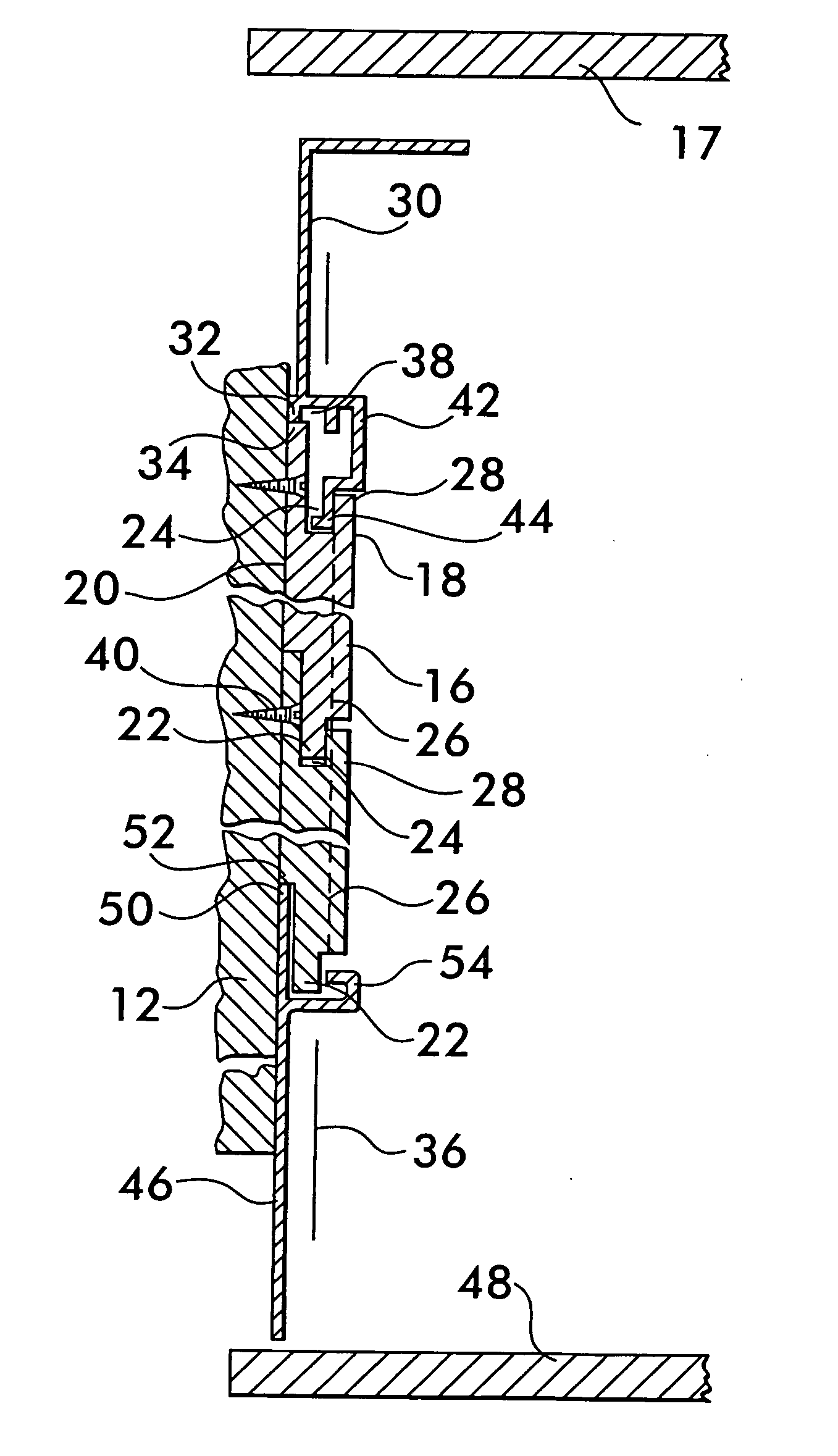
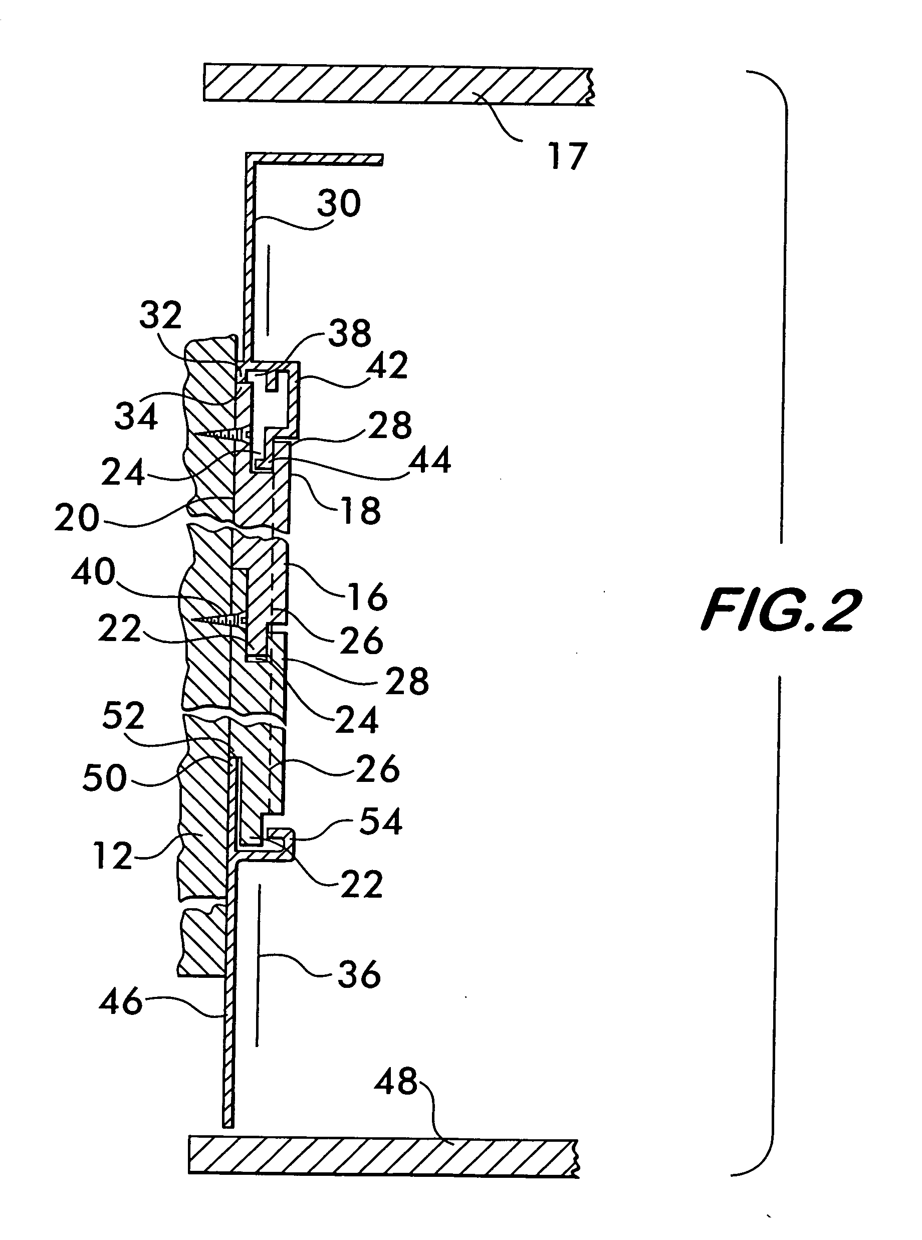
[0020] Panel assembly 10 is shown in detail in FIG. 2 and comprises one or more panels 16. Each panel has a front face 18 displaying a decorative surface and a back face 20 oppositely disposed to the front face. Back face 20 interfaces with the support structure 12 to which the panels are attached. Panels 16 preferably interlocked with one another using a tongue 22 and groove 24 positioned along opposite edges 26 and 28 of each panel. The panels are preferably interchangeable in that each has a tongue 22 positione...


PUM


Abstract

A panel assembly is disclosed having finishing elements in the form of trim plates. Interchangeable panels of the assembly having tongue and groove edges are attached to a support structure. The trim plates are positioned along free edges of panels at the top and bottom of the assembly. The trim plates have mounting surfaces that engage respective contact surfaces on the panels. The mounting and contact surfaces are offset away from a center plane of the panels toward a back face that interfaces with the support structure to which the panel assembly is attached. The offset provides enhanced structural safety by reducing bending moments on fasteners effecting attachment of the panel assembly to the support structure.

Description

FIELD OF THE INVENTION [0001] This invention relates to panel assemblies having trim plates especially useful to finish elevator cab interiors. BACKGROUND OF THE INVENTION [0002] In the construction of elevators, it is advantageous to provide an interior that is architecturally pleasing. This is often accomplished by mounting decorative panels onto the elevator cab or cage. The panels may display rich wood grain, mirrored surfaces, brushed steel or decorative embossments or moldings and serve to hide the functional appearance of the elevator cab. Trim plates, for example, kick plates positioned adjacent to the floor of the cab, and crown plates, positioned adjacent to the ceiling of the cab, are also useful to complete the cab interior. [0003] Decorative panels and the trim plates may be heavy and, therefore, require robust attachment to the supporting structure provided by the elevator cab. Because the elevator cab is not a static structure, the panels and trim plates are subjected...

Claims


Application Information

Patent Timeline
Patent Type & Authority Applications(United States)
IPC IPC(8): B66B11/02
CPCB66B11/0253
Inventor BOSTOCK, GLENN A.
Owner BOSTOCK GLENN A
Why Eureka
Try Eureka