

Terminal end-piece for a fuel assembly having an arrangement for maintaining the ends of the rods and corresponding assembly
a technology for fuel assemblies and end pieces, which is applied in the direction of nuclear engineering problems, nuclear elements, greenhouse gas reduction, etc., can solve the problems of vibration and damage to the fuel rods, and in particular the lower ends of the fuel rods
- Summary
- Abstract
- Description
- Claims
- Application Information
AI Technical Summary
Benefits of technology
Problems solved by technology
Method used
Image

Examples
Embodiment Construction
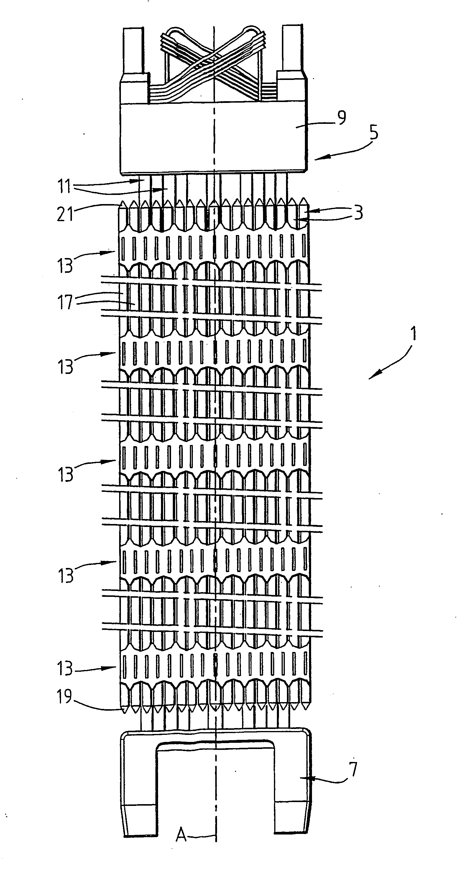
[0043] In order to illustrate the context of the invention, FIG. 1 schematically illustrates a nuclear fuel assembly 1 for a pressurised water reactor. Therefore, the water fulfils in that case a coolant and moderating function, for example, slowing down the neutrons produced by the nuclear fuel. The assembly 1 extends vertically and in a rectilinear manner in a longitudinal direction A.
[0044] Conventionally, the assembly 1 principally comprises nuclear fuel rods 3 and a structure or skeleton 5 for supporting the rods 3.
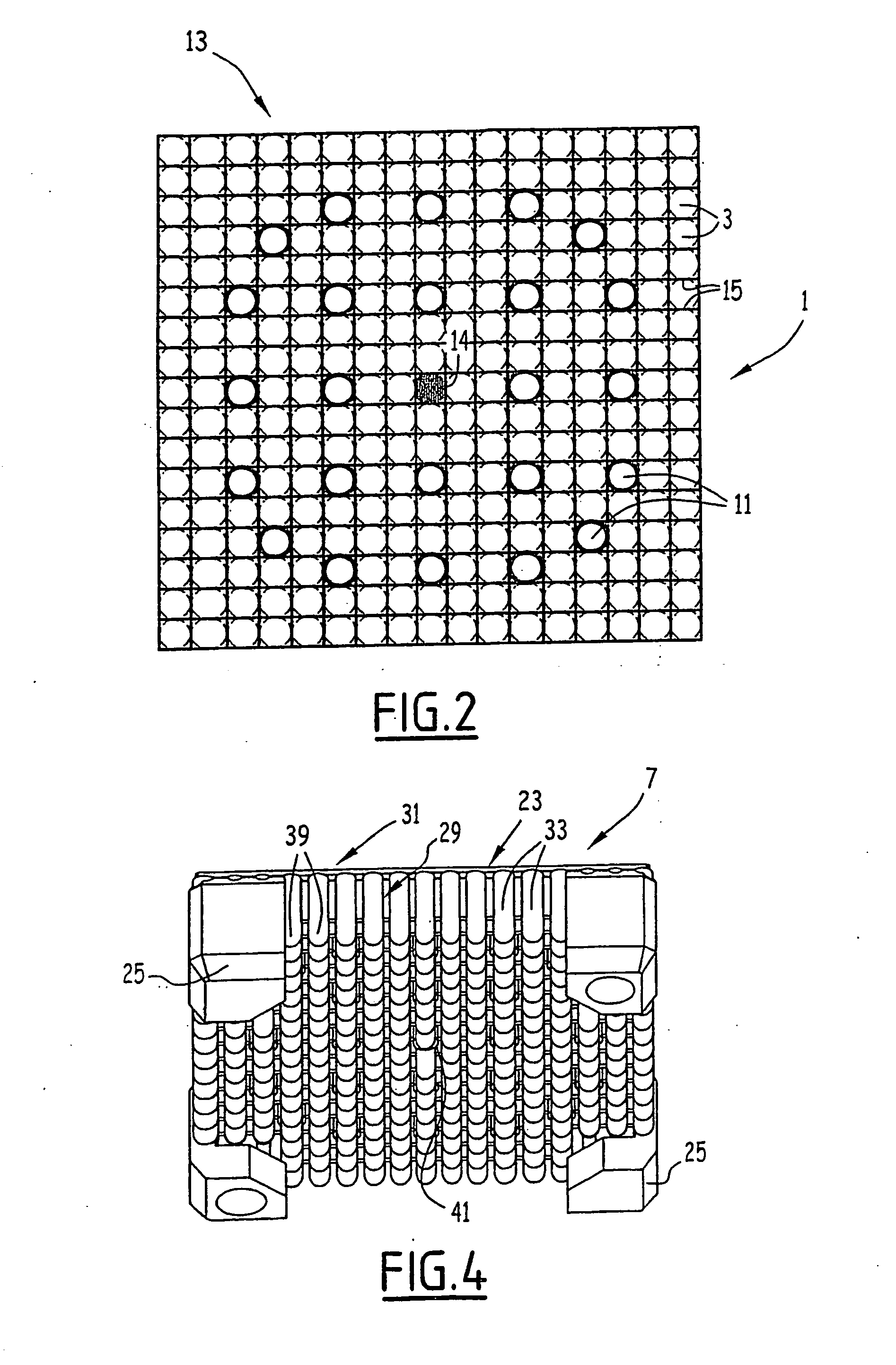
[0045] The support skeleton 5 conventionally comprises: [0046] a bottom end-piece 7 and a top end-piece 9 that are arranged at the longitudinal ends of the assembly 1, [0047] guide tubes 11 that are intended to receive the rods of an assembly for controlling and stopping the nuclear reactor and [0048] grids 13 for maintaining the rods 3.
[0049] The end-pieces 7 and 9 are fixed to the longitudinal ends of the guide tubes 11.
[0050] The rods 3 extend vertically betwe...
PUM
 Abstract
Description
Claims
Application Information