Nail clipper with nail collection mechanism

a nail clipper and collection mechanism technology, applied in the field of nail clippers, can solve the problems of unsanitary and unpleasant experience, difficulty in collecting and disposing loose nail clippings after nails have been neatly trimmed, and unable to meet the needs of cleaning, etc., to achieve the effect of efficient collection and disposal of nail clippings, simple and scalable design, and appropriate degree of flexibility

Inactive Publication Date: 2007-08-16
SUNDERLAND MICHAEL
View PDF17 Cites 4 Cited by
  • Summary
  • Abstract
  • Description
  • Claims
  • Application Information

AI Technical Summary

Benefits of technology

[0008]Another object of the present invention is to provide a nail clipper including an incorporated nail arrestor that prevents the unconstrained ejection and propulsion of cut nail clippings.
[0010]Still another object of the present invention is to provide a nail clipper that efficiently collects and discards nail clippings.
[0011]Another object of the present invention is to provide a nail clipper that allows users to discard loose nail clippings without having to touch the clippings.
[0012]Still another object of the present invention is to provide a nail clipper that possesses a simple and scalable design.
[0013]It is another object of the present invention to provide a nail clipper that is fabricated of lightweight materials providing an appropriate degree of flexibility, resiliency, durability, and longevity.
[0014]An additional object of the present invention is to provide a nail clipper that is inexpensive to manufacture and sell to provide for widespread use and disposability.

Problems solved by technology

Although the importance of trimming one's finger and toenails is undisputed, there is a drawback associated with this procedure.
Specifically, collecting and disposing loose nail clippings after the nails have been neatly trimmed can be difficult.
Handling nail clippings, even simply to toss them in a garbage bin can be an unsanitary and unpleasant experience.

Method used


Image

  • Nail clipper with nail collection mechanism
  • Nail clipper with nail collection mechanism
  • Nail clipper with nail collection mechanism

Examples


Embodiment Construction

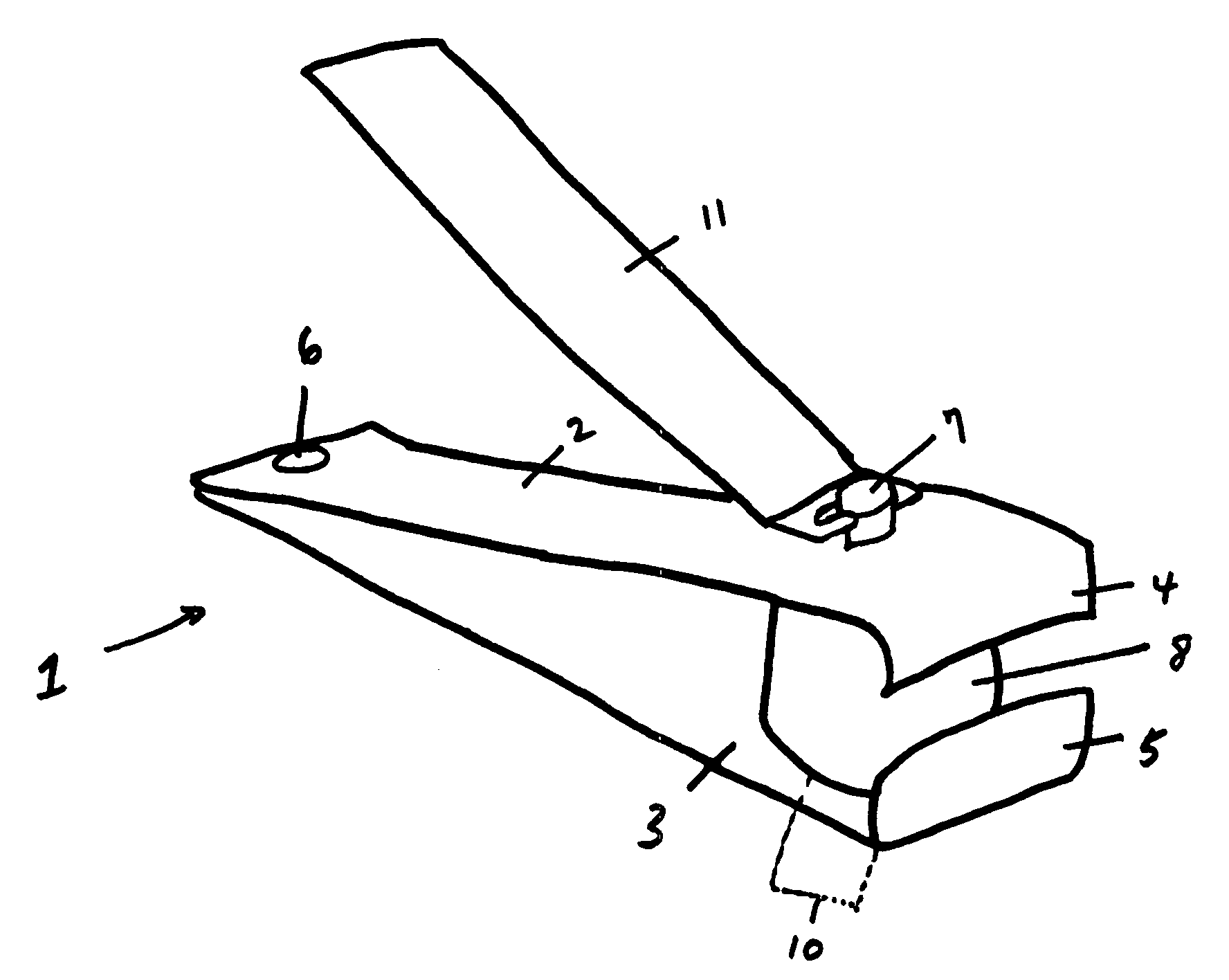
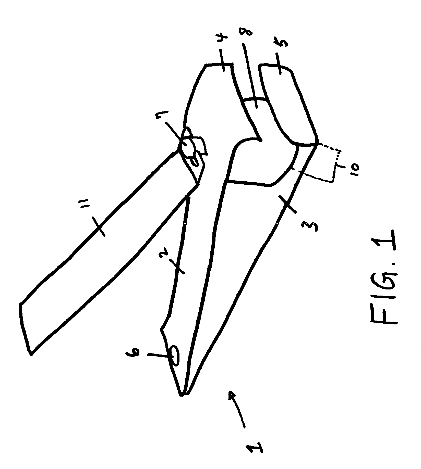
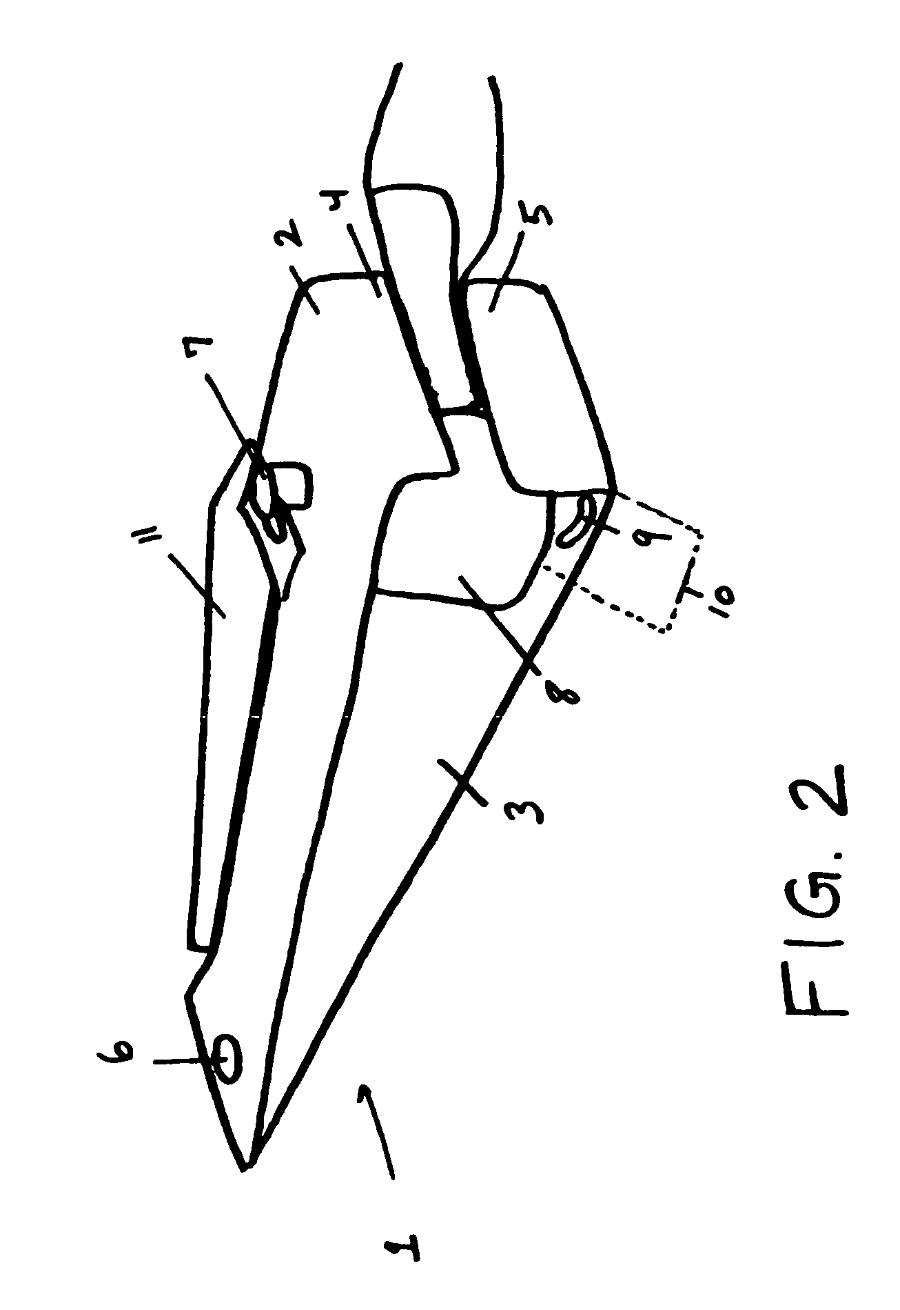
[0019]The present invention is a nail clipper 1 including an incorporated nail arrestor that prevents the unconstrained ejection and propulsion of cut nail clippings 9. FIG. 1 is a side perspective view of the clipper 1. The nail clipper 1 largely comprises a conventional nail clipper including a first plate 2 and a second plate 3. First plate 2 includes a down turned cutting edge 4 and a second plate 3 includes an upturned cutting edge 5 at one end. The cutting edges 4, 5 may be slightly contoured, having a crescent shape, which accommodates the natural shape of the fingernail and toenail. A bore (not shown) is drilled through the opposing end of both plates 2, 3. A pin 6 is inserted through the bores to connect first 2 and second 3 plates together. Alternately any suitable means may be utilized to connect said first 2 and second 3 plates together, such as welding or gluing. A bore (not shown) is drilled into each of first 2 and second plates 3 at a spaced distance behind the cutti...


PUM


Abstract

The present invention is a nail clipper including an incorporated nail arrestor that prevents the unconstrained ejection and propulsion of cut nail clippings. The nail clipper includes two steel plates connected at one end and with cutting edges at an opposing end, and an operating lever, which moves the cutting edges of the plates together. A pivot pin is inserted through bores in both first and second plates, at a spaced distance behind the cutting edges. A grommet encircles the portion of the pin between the plates and maintains a spaced distance between the plates to form an opening for receiving a nail. The space between the foam and the topside of the second plate forms a receptacle for receiving nail clippings after they fall downwards from the cutting edges. The clippings may be emptied directly into a trash bin by tilting the nail clipper sideways.

Description

CROSS-REFERENCE TO RELATED APPPLICATION[0001]The present application derives priority from U.S. provisional application No. 60 / 772,128 filed 25 Jan. 2006.BACKGROUND OF THE INVENTION[0002]1. Field of the Invention[0003]The present invention relates to nail clippers and, more particularly, to an improved nail clipper including an incorporated nail arrestor that prevents the unconstrained ejection and propulsion of cut nail clippings.[0004]2. Description of the Background[0005]A key component of a well-groomed appearance is a set of carefully trimmed nails. While cosmetically attractive nails that are clean and neatly trimmed are also an important factor in a person's overall health. Although the importance of trimming one's finger and toenails is undisputed, there is a drawback associated with this procedure. Specifically, collecting and disposing loose nail clippings after the nails have been neatly trimmed can be difficult. Most fingernail clippers feature sharp blades, which clamp ...

Claims


Application Information

Patent Timeline
Patent Type & Authority Applications(United States)
IPC IPC(8): A45D29/00
CPCA45D29/023
Inventor SUNDERLAND, MICHAEL
Owner SUNDERLAND MICHAEL
Why Eureka
Try Eureka