Garment hanger

Inactive Publication Date: 2007-08-23
WU RAYMOND
View PDF15 Cites 8 Cited by
  • Summary
  • Abstract
  • Description
  • Claims
  • Application Information

AI Technical Summary

Benefits of technology

[0006] It is an object of the present invention to provide a garment hanger which h

Problems solved by technology

This brings a limit to exhibition and display of the garments on the garment hangers.

Method used


Image

  • Garment hanger
  • Garment hanger
  • Garment hanger

Examples


Embodiment Construction

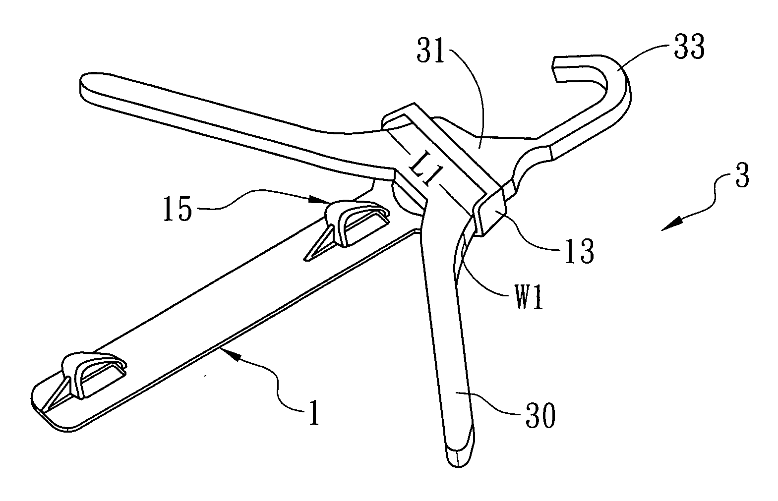
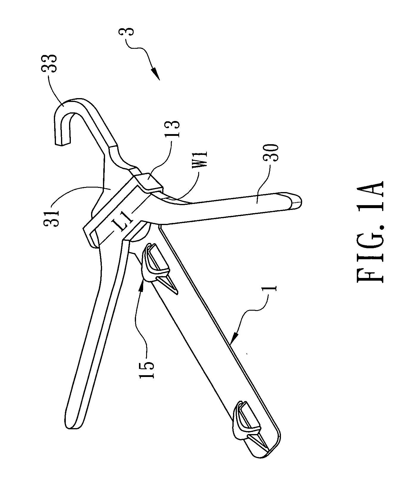
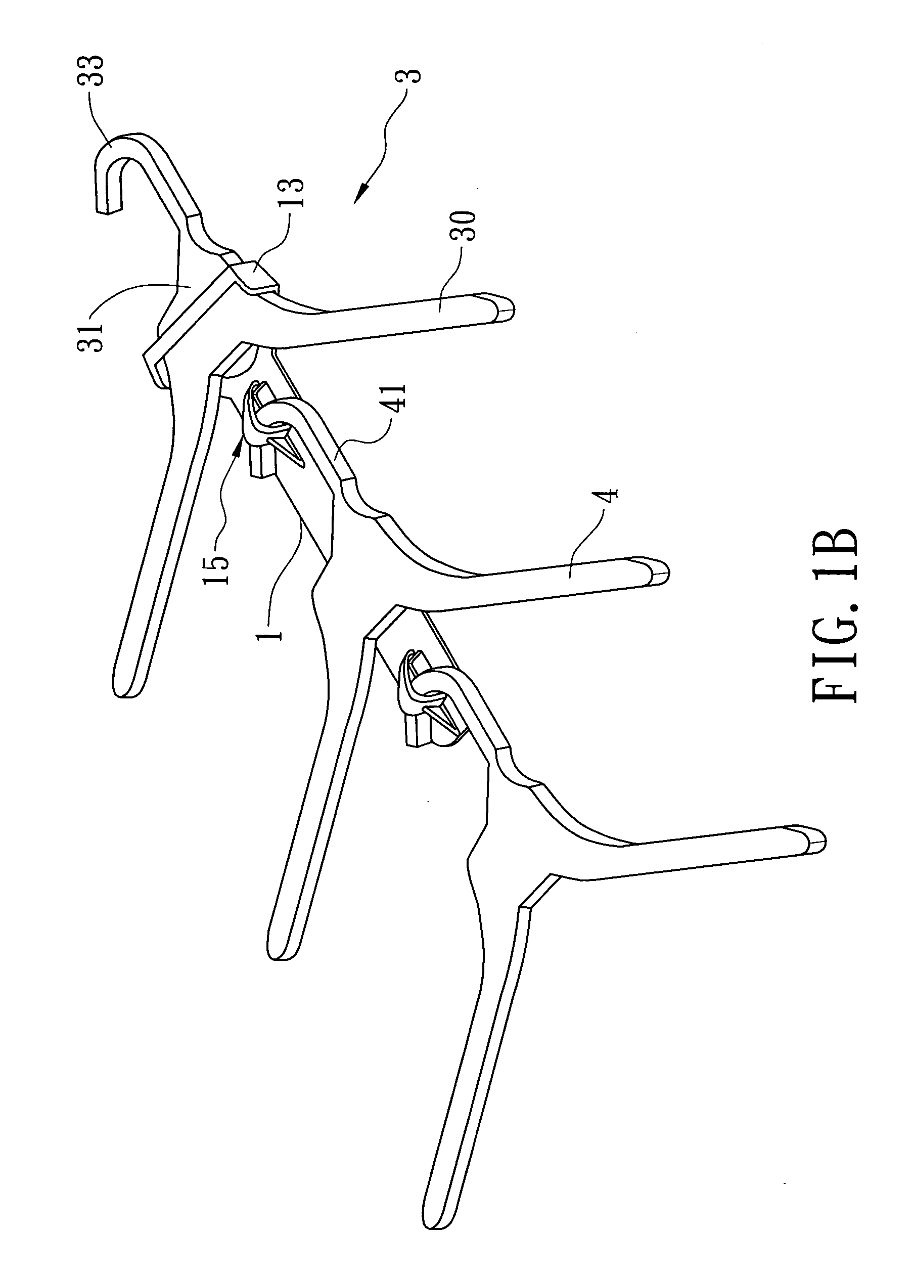
[0020]FIG. 1A is a perspective view of a preferred embodiment of a garment hanger 3 in accordance with the present invention. As shown in FIG. 1A, the garment hanger 3 includes a hanger body 30 and a linking piece 1 attachable to the hanger body 30 in a suspended manner.

[0021] The hanger body 30, configured approximately as an inverted V, a triangle or as any shape which can support a garment on it, may be made of plastic by injection or of any other durable material suitable for it. Additionally, the hanger body 30 has a neck 31 from which a hook 33 extends.

[0022] Referring to FIG. 2, the linking piece 1 may also be made of plastic by injection or of any other durable material suitable for it. The linking piece 1 includes a main body 11 having a top annular portion 13 formed on the main body 11 at a right angle. Particularly, the annular portion 13 is adapted to be detachably mounted around the neck 31 of the hanger body 30, as clearly shown in FIG. 1A, for hanging the linking pi...


PUM


Abstract

A garment hanger includes a hanger body and a linking piece attachable to the hanger body in a suspended manner. The hanger body has a neck from which a hook extends. The linking piece includes a main body having an annular portion adapted to be detachably mounted around the neck of the hanger body, and a plurality of spaced holders formed on the main body for hanging other garment hangers therefrom.

Description

FIELD OF THE INVENTION [0001] The present invention relates to a garment hanger and, more particularly, to a garment hanger which has a linking piece for hanging other garment hangers therefrom. BACKGROUND OF THE INVENTION [0002] A garment hanger provided with a linking element known in FIG. 5 showing a perspective view of an exiting garment hanger 5, which includes a curved body 51 formed with an upper hook 52 and a lower linking element 53. In general, the linking element 53 has a ringlike configuration used for hanging hook 62 of another garment hanger 6. [0003] Although the garment hanger 5 provides a linkage between the two, it can not be used for hanging more than one garment hangers directly from it. [0004] Furthermore, the ringlike element 53 defines an eye extending in a direction as designated by the arrow 531, which is substantially parallel to the curved body 51, for hanging up the other garment hanger 6, so that the two garment hangers linked up are oriented in the same...

Claims


Application Information

Patent Timeline
IPC IPC(8): A41D27/22
CPCA47G25/186A47G25/1442
Inventor WU, RAYMOND
Owner WU RAYMOND
Why Eureka
Try Eureka