Bag and hanger carrying grip

a bag and hanger technology, applied in the direction of sacks, hoisting equipment, transportation and packaging, etc., can solve the problems of less convenient plastic bags and bag pulling, and achieve the effect of convenient installation and removal of plastic bags

Inactive Publication Date: 2007-06-19
PORTER FAY
View PDF40 Cites 32 Cited by
  • Summary
  • Abstract
  • Description
  • Claims
  • Application Information

AI Technical Summary

Benefits of technology

[0005]A rigid carrying grip facilitates installation and removal of plastic bags in the grip and remains installed on the bags when the bags are not being carried. The carrying grip is made up of a tubular section terminating at first and second ends. The tubular section includes a slit along its axial length between the first and second ends.

Problems solved by technology

While plastic bags are stronger, lighter, and more impervious to weakening due to moisture, plastic bags can be less convenient for a number of reasons.
For example, when the plastic bag is heavily loaded, the handle of the bag is pulled taut and takes on characteristics of a wire or string that is uncomfortable to carry.

Method used


Image

  • Bag and hanger carrying grip
  • Bag and hanger carrying grip
  • Bag and hanger carrying grip

Examples


Embodiment Construction

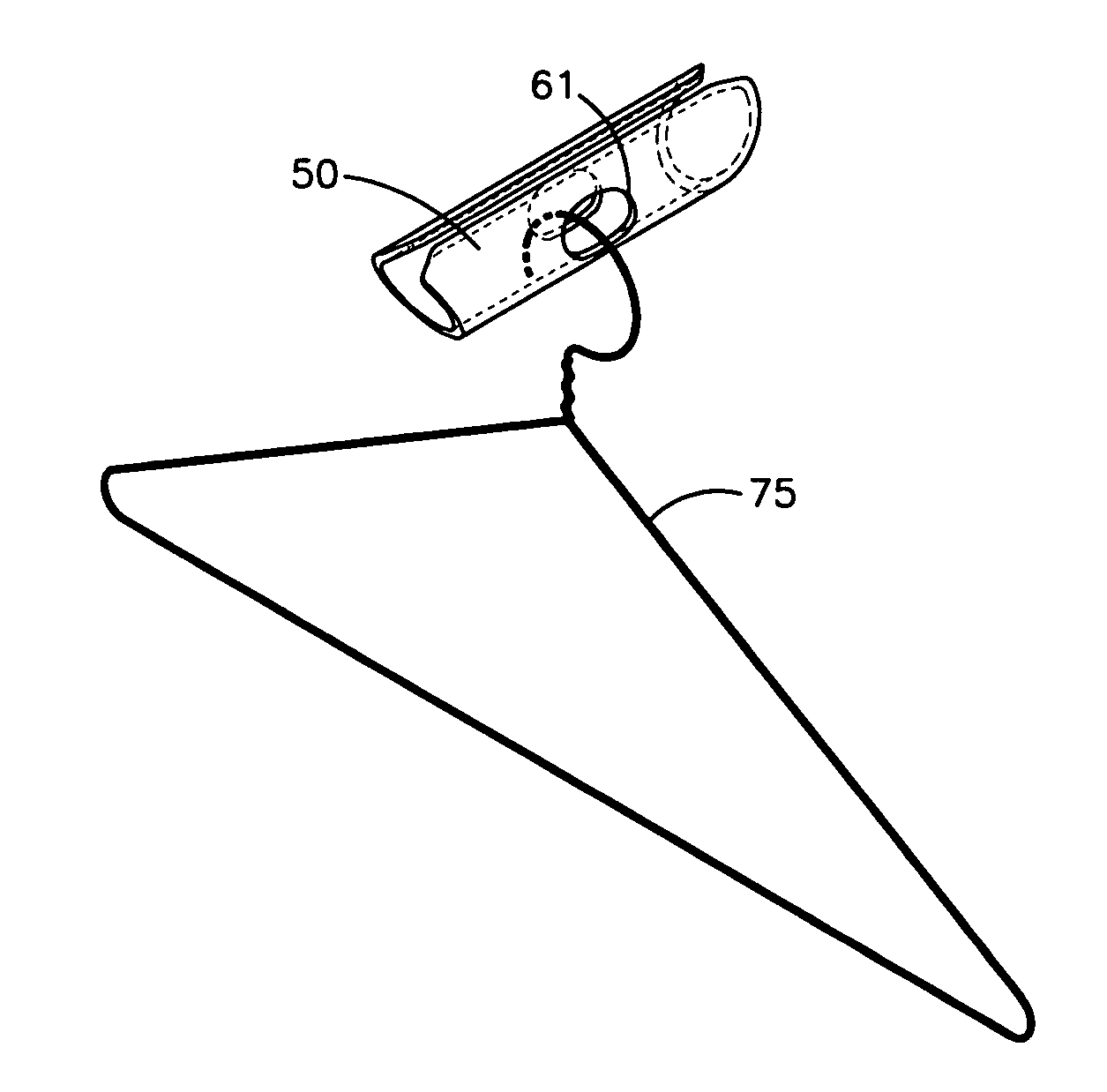
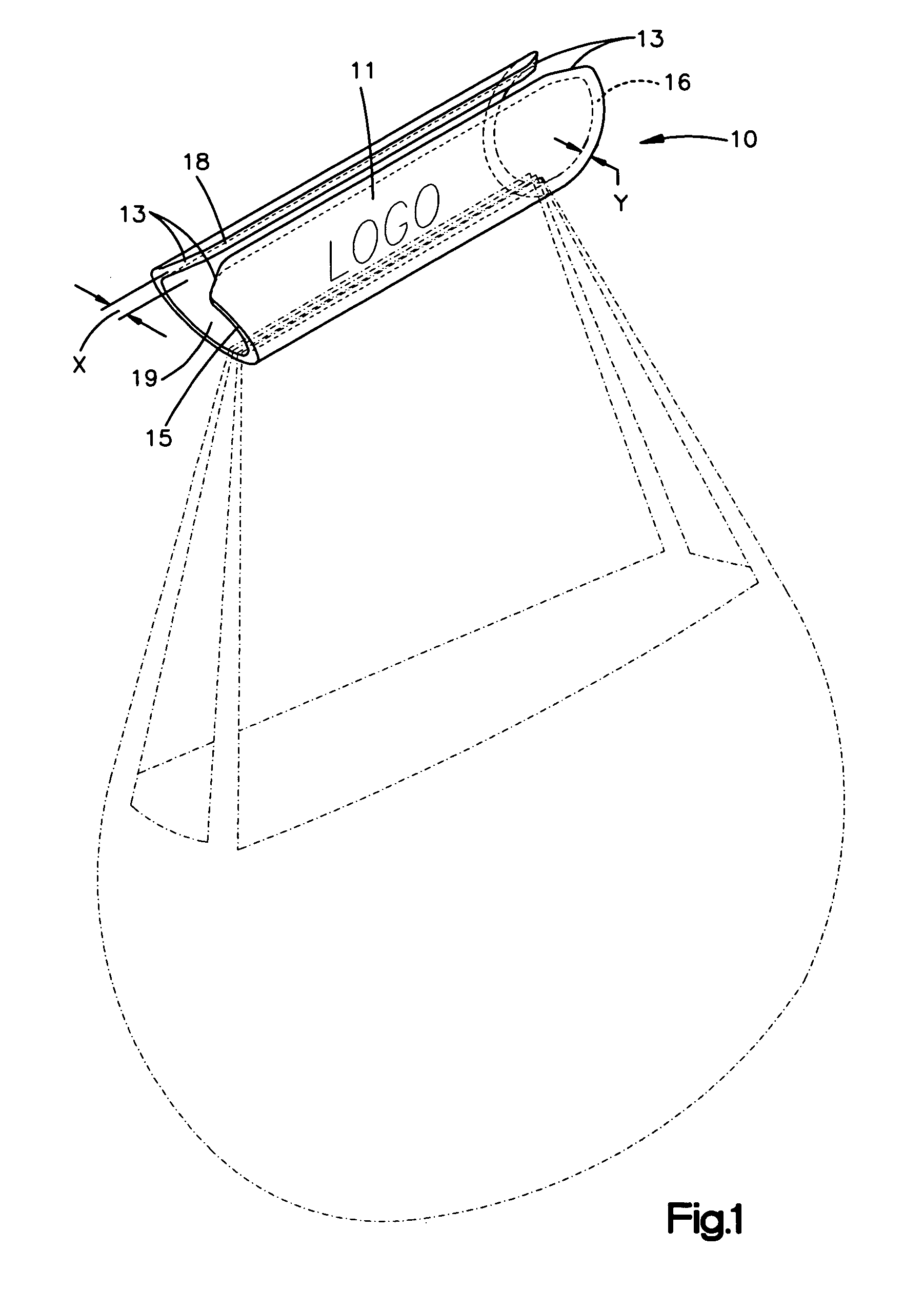
[0018]Referring to FIG. 1, a bag carrying grip 10 is shown in a perspective view with a bag illustrated in phantom. The grip 10 is made up of a tubular section 11 having a length of about four inches and an outer diameter of about one inch and an inner diameter of about ⅞ inch. The tubular section 11 terminates in end surfaces 15, 16 at either end. The tubular section 11 can be molded or machined from tube stock such as PVC plastic. While a tubular member having a circular cross section is shown herein, it will be apparent to one of skill in the art that a tubular section having a different cross sectional shape such as oval, square or triangular may also be employed. The tubular member has a wall thickness designated “y” in FIG. 1 which is less than ½ inch, preferably less than or equal to ⅛ inch. A slit 18 runs the length of the tubular section to provide an access opening for bags that are to be installed in the grip 10. The slit has a width “x” that is less than ½ inch, preferab...


PUM


Abstract

A bag carrying grip facilitates installation and removal of plastic bags in the grip and remains installed on the bags when the bags are not being carried. The carrying grip includes a rigid, generally tubular section having tapered ends and a slit running the length of the tubular section. Bags are inserted in the slit and can remain in the slit until the user removes them. The carrying grip may also include a pair of opposed hanger carrying openings that form a passage through which one or more hangers may be passed to ease in carrying the hangers. The hangers will remain installed in the grip until removed by the user.

Description

CROSS REFERENCE TO RELATED APPLICATIONS[0001]This application claims the benefit of priority from U.S. Provisional Application Nos. 60 / 726,576 filed on Oct. 14, 2005 and 60 / 817,166 filed on Jun. 28, 2006.TECHNICAL FIELD[0002]The invention relates generally to the field of articles for personal assistance in carrying loads and more particularly to articles for assisting persons in carrying one or more bags with handles or handle openings and / or clothing hangers.BACKGROUND OF THE INVENTION[0003]While in the past the use of paper bags or sacks was common, increasingly, plastic bags are replacing paper bags in retail establishments. The plastic bags often include an integral handle formed by two opposing openings near the top of the bag. While plastic bags are stronger, lighter, and more impervious to weakening due to moisture, plastic bags can be less convenient for a number of reasons. For example, when the plastic bag is heavily loaded, the handle of the bag is pulled taut and takes ...

Claims


Application Information

Patent Timeline
Patent Type & Authority Patents(United States)
IPC IPC(8): A45F5/10B65D33/06
CPCA45F5/1026A45F2005/1033
Inventor PORTER, FAY
Owner PORTER FAY
Why Eureka
Try Eureka