LED module and illumination device

a technology of led modules and led modules, which is applied in the direction of semiconductor devices for light sources, light and heating apparatus, refractors, etc., can solve the problems of poor sealing effect, poor leakage resistance, poor etc., and achieves good leakage resistance, good sealing performance of led modules, and convenient installation and removal

Active Publication Date: 2018-02-15
HANGZHOU HPWINNER OPTO CORP
View PDF3 Cites 11 Cited by
  • Summary
  • Abstract
  • Description
  • Claims
  • Application Information

AI Technical Summary

Benefits of technology

[0032]1) Regarding the LED provided in the present invention, the lens assembly and the base therein are connected by means of threads, and both are cylindrical at the threaded connection. Moreover, the matching sealing ring is disposed, thereby achieving good sealing performance of the LED module. Compared to the connection ways such as using a screw or a snap fitting in the prior art, the force bearing surface between the lens assembly and the base in the present invention is increased and even force bearing is achieved, resulting in a secure connection and good leakproofness between the lens assembly and the base. Furthermore, the threaded connection way facilitates installation and removal of the lens assembly and the base.
[0033]2) Regarding the LED module provided in the present invention, the first matching structure and the second matching structure are disposed at the connections of the lens assembly and the base, respectively. The stepped sealing ring is disposed between the first matching structure and the second matching structure, and preferably, the sealant is also provided therebetween, thus leading to a good sealing effect between the lens assembly and the base.
[0034]3) Regarding the LED module provided in the present invention, the third matching structure and the fourth matching structure are disposed at the connections of the lens assembly and the base, respectively. The wed

Problems solved by technology

Such connection ways have disadvantages such as troublesome installation, easy loosing, and insecure connection, which may then affect the sealing performance between the lens assembly and the radiator, resulting in a poor sealing effect.
In addition, the connection using

Method used


Image

  • LED module and illumination device
  • LED module and illumination device
  • LED module and illumination device

Examples


embodiment 1

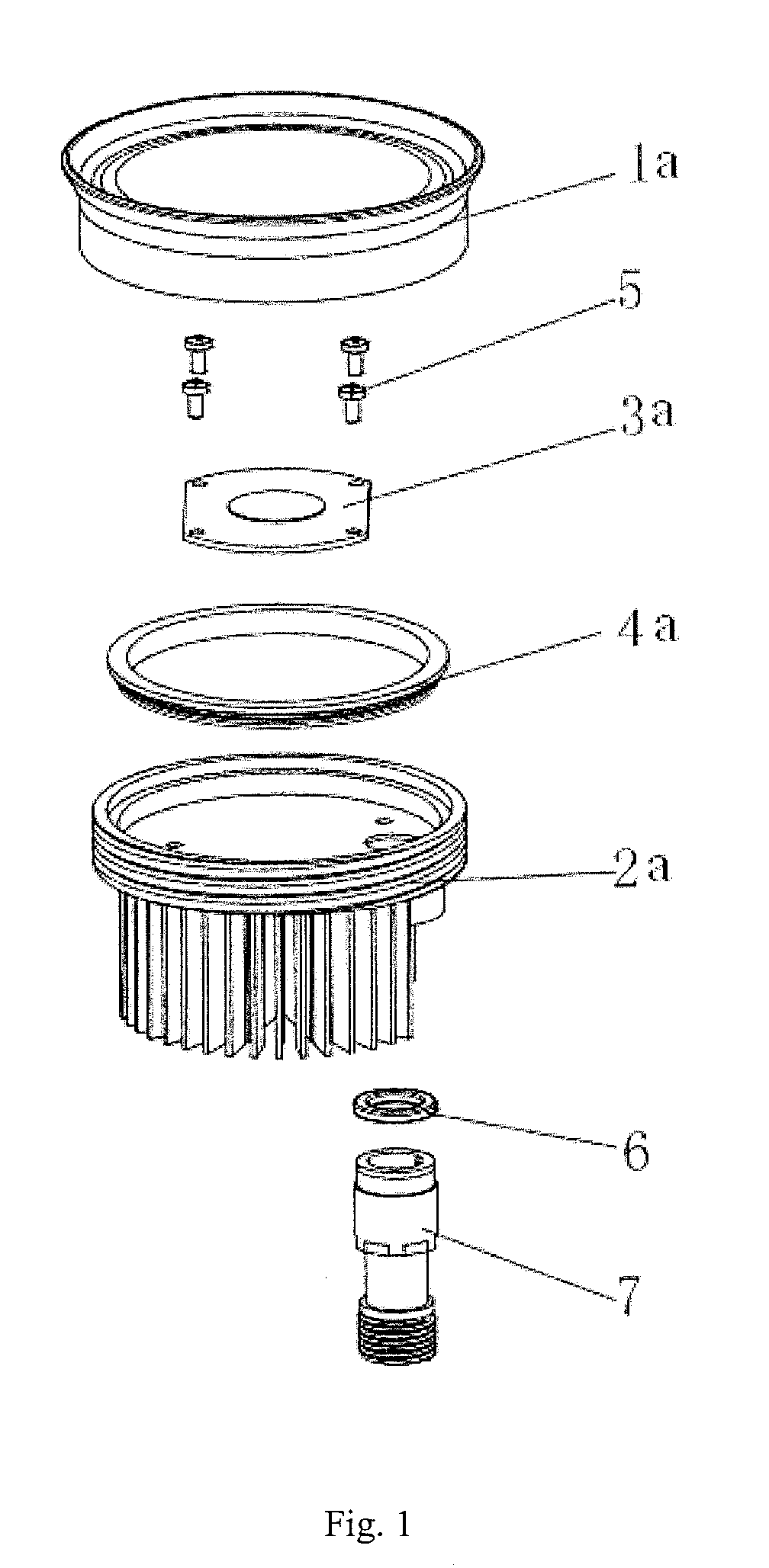
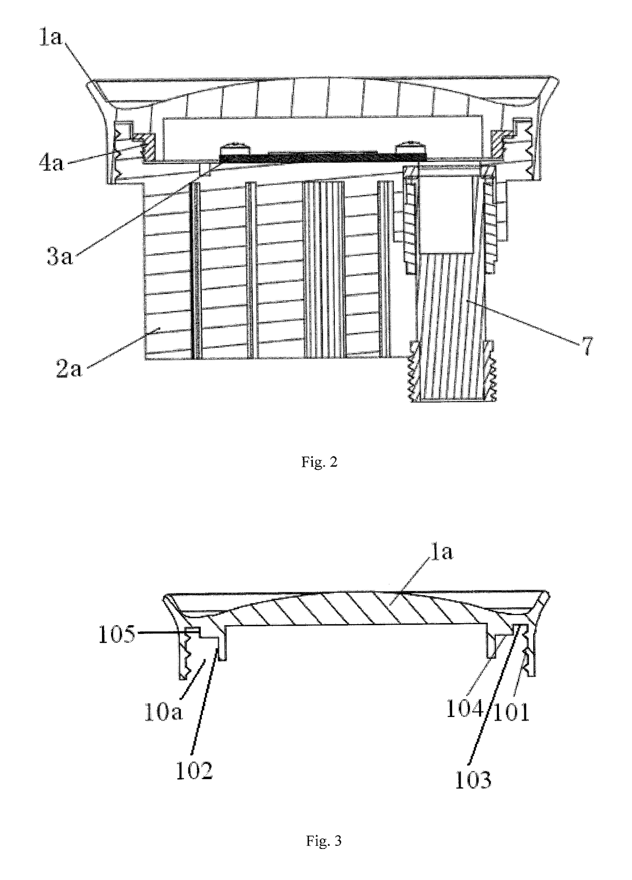
[0053]Referring to FIG. 1 and FIG. 2, the present embodiment provides an LED module. The LED module comprises a lens assembly, a base 2a, and a light source assembly 3a, wherein the lens assembly is provided with an internal thread, while the base 2a is correspondingly provided with an external thread matching the internal thread, and the lens assembly and the base 2a are connected by means of the threads to form a closed accommodating space therebetween. Moreover, a sealing ring is also disposed at a portion between the threaded connection of the base and the lens assembly and the accommodating space. The light source assembly 3a is located in the accommodating space, and disposed at one side of the base 2a. Specifically, the light source assembly 3a may be composed of a substrate and a plurality of LED light emitters disposed on the substrate. The substrate may be, for example, a PCBA. Certainly, the specific structural form of the light source assembly is not limited to this, and...

embodiment 2

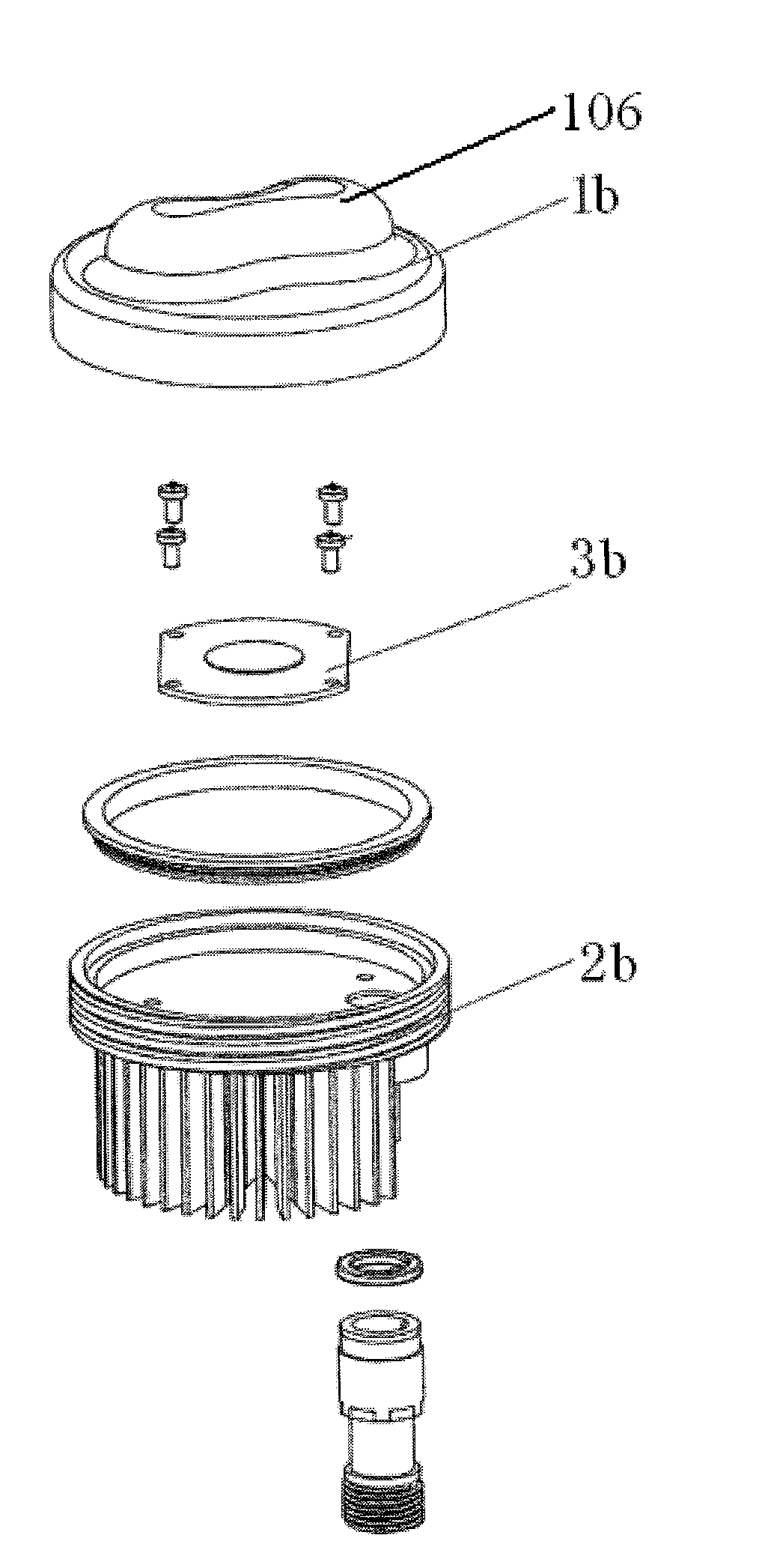
[0085]Referring to FIG. 6, the embodiment provides an LED module comprising a lens assembly, a base 2b, and a light source assembly 3b. The lens assembly is installed on the upper end face of the base 2b, and the two are connected by means of threads to form a closed accommodating space therebetween. The light source assembly 3b is located in the accommodating space. A plurality of fins are disposed on the lower end of the base 2b for dissipating heat.

[0086]In this embodiment, the lens assembly is a light distribution lens 1b. A protruding light distribution structure 106 is disposed on the upper end of the lens such that the light module may be applied to a streetlamp and also to other lamps needing light distribution, which is not limited herein. The protruding light distribution structure 106 of the lens 1b is asymmetrical, and an installation direction of the lens 1b in the circumferential direction may be determined according to a light irradiation direction requirement. Other ...

embodiment 3

[0088]Referring to FIG. 7 and FIG. 8, this embodiment provides an LED module comprising a lens assembly, a base 2c, and a light source assembly 3c. The lens assembly is installed on the upper end face of the base 2c, and the two are connected by means of threads to form a closed accommodating space therebetween. The light source assembly 3c is located in the accommodating space. A plurality of fins are disposed on the lower end of the base 2c to form a radiator for dissipating heat.

[0089]In this embodiment, as shown in FIG. 7, the lens assembly is composed of a lens 1c and a lens pressing ring 8, wherein the lens pressing ring 8 is preferably made of a metal material so that the lens pressing ring 8 can have good strength and be prevented from damage such as cracks. The lens 1c is provided with an edge portion and a lens portion protruding up with respect to a radial circumferential surface of the edge portion, wherein the radial size of the edge portion is greater than that of the ...


PUM


Abstract

An LED module having a base, a lens assembly, and a light source assembly. The lens assembly has an internal thread and the base has a matching external thread. The lens assembly and base are connected by the threads to faun a closed accommodating space. A sealing ring is disposed at a portion between the thread connection of the base, lens assembly, and accommodating space. The light source assembly is in the accommodating space and at one side of the base. The lens assembly and the base are in threaded connection, providing an increased force bearing surface and even force bearing therebetween, resulting in a secure connection, good leakproofness, and convenient installation and removal. The sealing ring is disposed at the connection of the lens assembly and the base, allowing for an excellent sealing effect between the lens assembly and the base.

Description

TECHNICAL FIELD[0001]The present invention relates to the technical field of lighting device design, and in particular to an LED module and a lighting device.BACKGROUND ART[0002]An LED lamp has the advantages of energy saving, long service life, good adaptability, short response time, environmental friendliness and so on, and is the trend of development of the lighting industry. An LED module is an essential part-of an LED lamp, and typically, the LED module is constituted by a lens assembly, a light source assembly, and a radiator, with the light source assembly being disposed on the radiator and the lens assembly being disposed to cover the radiator such that the light source assembly being disposed between the lens assembly and the radiator.[0003]In the prior art, the lens assembly is typically connected to the radiator using a screw, in a snap-fitting way, or the like. Such connection ways have disadvantages such as troublesome installation, easy loosing, and insecure connection...

Claims


Application Information

Patent Timeline
IPC IPC(8): F21V17/12F21V5/04F21V29/77F21V31/00
CPCF21V17/12F21V31/005F21V5/04F21V29/773F21Y2115/10F21K9/00F21V19/0055F21V23/06F21V29/74
Inventor CHEN, KAIHUANG, JIANMING
Owner HANGZHOU HPWINNER OPTO CORP
Why Eureka
Try Eureka