

Fin attachment system and method
a technology of attachment system and fin, which is applied in the field of fins, can solve the problems of limited choice and least the number of fin boxes fitted to the board
- Summary
- Abstract
- Description
- Claims
- Application Information
AI Technical Summary
Problems solved by technology
Method used
Image

Examples
first preferred embodiment
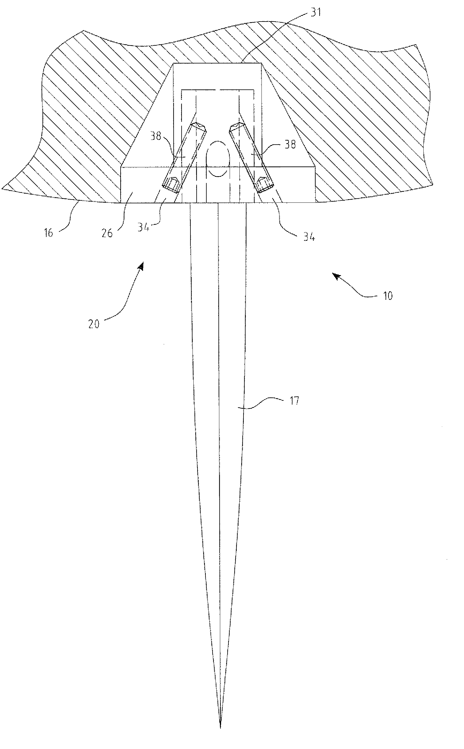
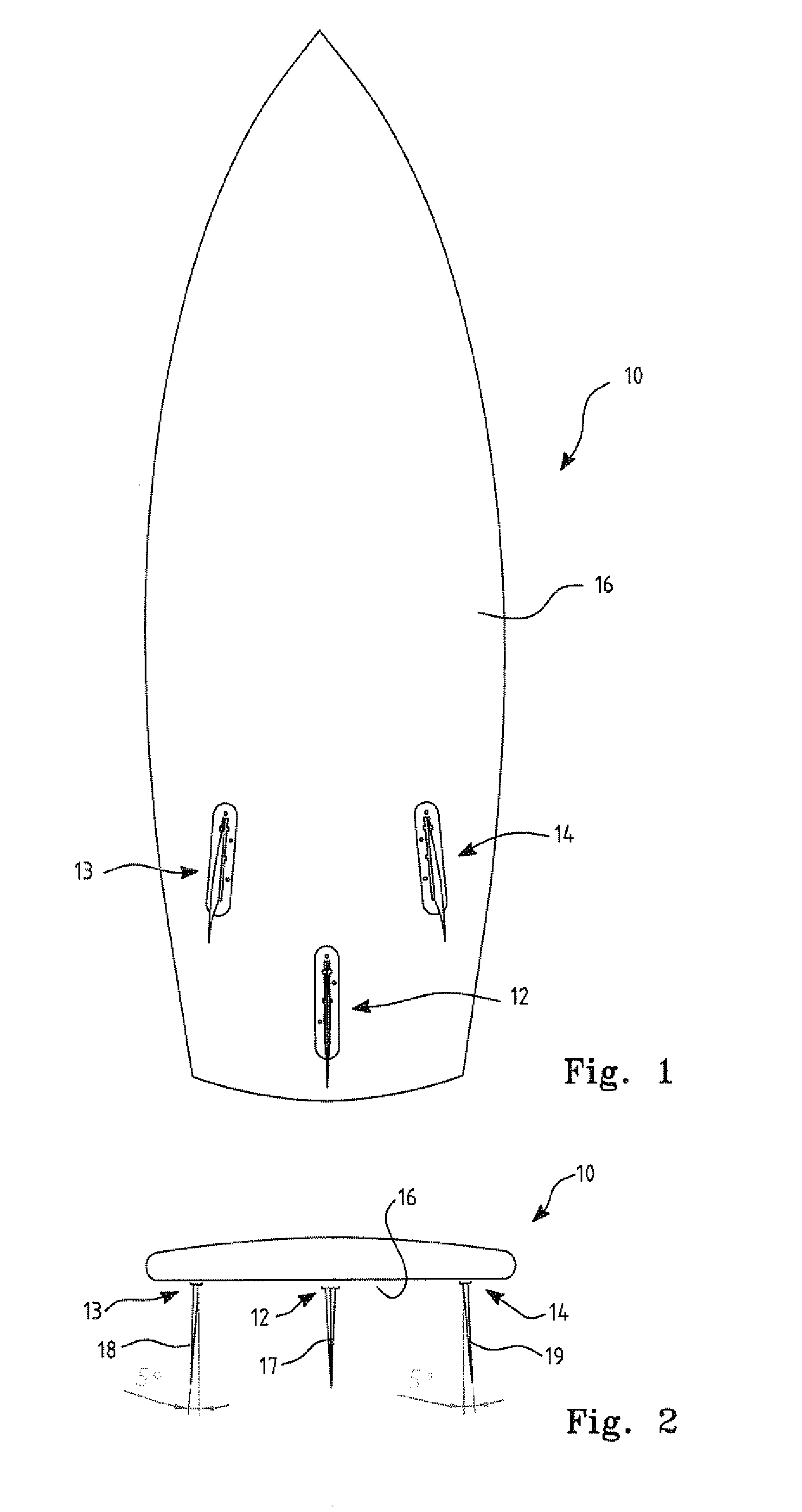
[0056] In a first preferred embodiment of the invention and with reference to FIGS. 1 and 2, a surfboard 10 is fitted with three fin retaining structures 12, 13 and 14, commonly known as fin boxes, embedded into the underside 16 of surfboard 10. Fin box 12 provides for a center fin 17, while fin boxes 13 and 14 accommodate left outside fin 18 and right outside fin 19 respectively.
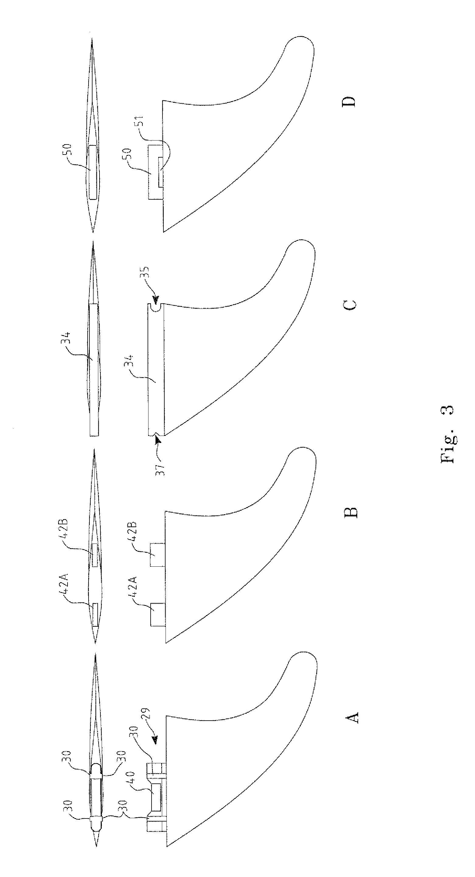
[0057] Fins 17, 18 and 19 are held in retaining structures of fin boxes 12, 13 and 14 by a fin-tab formed at the top edge of the fin, that is that edge of the fin substantially flush with the surface of the underside of the surfboard. Examples of typical fins and fin-tabs commercially available are shown in FIG. 3.
[0058] Referring again to FIG. 2, it will be noted that while center fin 17 has its central plane normal to the underside 16 of surfboard 10, the left and right outside fins are canted outwardly relative to that plane. That canting is generally at an angle of 5 degrees. Canting of outside fins m...
second preferred embodiment
[0070] In a further preferred embodiment of the invention, the fin boxes are somewhat simplified from those described above and shown in FIGS. 6 to 8 and FIGS. 11 and 12. In this embodiment the left, right and center fin boxes cater for fins with the fin tab configurations of FIGS. 3B and 3C.
[0071] With reference to FIG. 17, a center fin box 300, right hand fin box 304 and left hand fin box 302 (as viewed in FIG. 17) are each formed as before, as an elongate body 306 provided with a central recess 308 and a peripheral flange 310. As can be seen in the sectioned views of each of FIGS. 17A to 17C, recesses 308 extend from a first outer surface 316 to proximate an opposite inner surface 314. Shown as dashed lines in FIG. 17, and as best seen in FIG. 18, the recess 308 of this embodiment is also provided with a retaining structure 319 projecting from the rearward end wall 311.
[0072] First outer surface 316 comprises a first inner portion of peripheral flange 310 around recess 308. An ...
third preferred embodiment
[0094] Turning now to FIGS. 20 and 21, in this further preferred embodiment of the invention, as for the second preferred embodiment described above, a right hand fin box 404, center fin box 402 and a left hand fin box 400 are provided, all with the same general external configuration of the fin boxes of the second preferred embodiment shown in FIG. 17.
[0095] However, in this embodiment, the peripheral flange 420 of left side fin box 400, and the flange 424 of right side fin box 404 have a non-symmetrical profile, so as to provide additional support to the flange area containing the screw holes, and differ from the flange 422 of the center fin box 402 in that they are not axially aligned with the recess 408 or surface 416 of their respective fin boxes, as shown in FIG. 20A.
[0096] Additionally, the central recess 408 of each fin box is shortened to a length equal to that from leading edge 420 of the forward fin-tab 421 of a dual fin-tab fin 426, to the trailing edge 422 of the rear...
PUM
 Abstract
Description
Claims
Application Information