Water-filled flood bags for emergency flood control

a flood control and flood bag technology, applied in the direction of doors/windows, coastline protection, door/window protective devices, etc., can solve the problems of insufficient time to fill sandbags, inability to quickly respond to floodwater, and inability to fill sandbags in time, so as to minimize the damage of the floodwater, the effect of minimizing the damage of the cell and minimizing the punctur

Inactive Publication Date: 2007-10-18
TYLER TIM RICHARD
View PDF2 Cites 31 Cited by
  • Summary
  • Abstract
  • Description
  • Claims
  • Application Information

AI Technical Summary

Benefits of technology

[0049]In yet another embodiment of the invention an emergency flood control apparatus is presented having means for forming a plurality of vertical cells horizontally arranged, means for forming a horizontal tube adjacent to the cells, and means for connecting the cells to the tube such that the cells may be filled from fluid in the tube at substantially the same time. Further embodiments include means for clamping ends of the tube, means for attachment to structures, means for forming a plurality of layers of vertical cells, and means for minimizing punctures to the cells and seepage between layers.
[0050]In yet another embodiment of the invention, an emergency flood control apparatus includes two rows of a plurality of vertically separated cells horizontally arranged formed between at least two continuous sheets of impermeable flexible material, the rows forming a tandem layer of cells, a continuous horizontal tu...

Problems solved by technology

However, the filling and transporting of sand-filled bags to a flooded area is time-consuming, labor intensive and often impractical for rapid response in emergency situations.
Often there simply is not enough time to fill sandbags in an emergency.
Also, the soil in flooded areas may be too soft and muddy for filling sandbags and sand may have to be trucked to the site from other locations.
In some cases the soil in the flooding area is too soft to support heavy equipment and it simply becomes impossible to get suitable sand to the necessary location.
Further, after sandbags have been used they are soggy, muddy and saturated with floodwater that has often been contaminated with sewage and toxic waste.
While this approach reduces the need for sand at the flood site, bags of this type pose considerable expense and are still time-consuming and labor intensive to deploy because each bag must be individually filled and stacked.
However, after these devices become soaked, they cannot later be moved or removed feasibly for days or even weeks.
In addition, since these devices necessarily become soaked with floodwaters that may be contaminated with sewage and toxic waste, this results in a large quantity of contaminated material that may pose a serious waste disposal problem.
Since these fabric dams must be stretched perpendicularly across flowing water to work, they appear to only be applicable to large-scale straight-line situations and cannot be used to surround structures or form curved flood control structures around obstacles.
But these approaches depend on water pressure to inflate them to pre-determined lengths and circumferences, and this necessarily produces stiff linear, horizontal cells of predetermined length that are not well-adapted to small scale applications, to curve around obstacles, or to turn sharp corners.
Further, known methods utilizing horizontal water-filled ‘tubes’ or cells are configured such that any puncture or rupture of the external membrane of the tube at any location necessarily causes the entire l...

Method used


Image

  • Water-filled flood bags for emergency flood control
  • Water-filled flood bags for emergency flood control
  • Water-filled flood bags for emergency flood control

Examples


embodiment 1

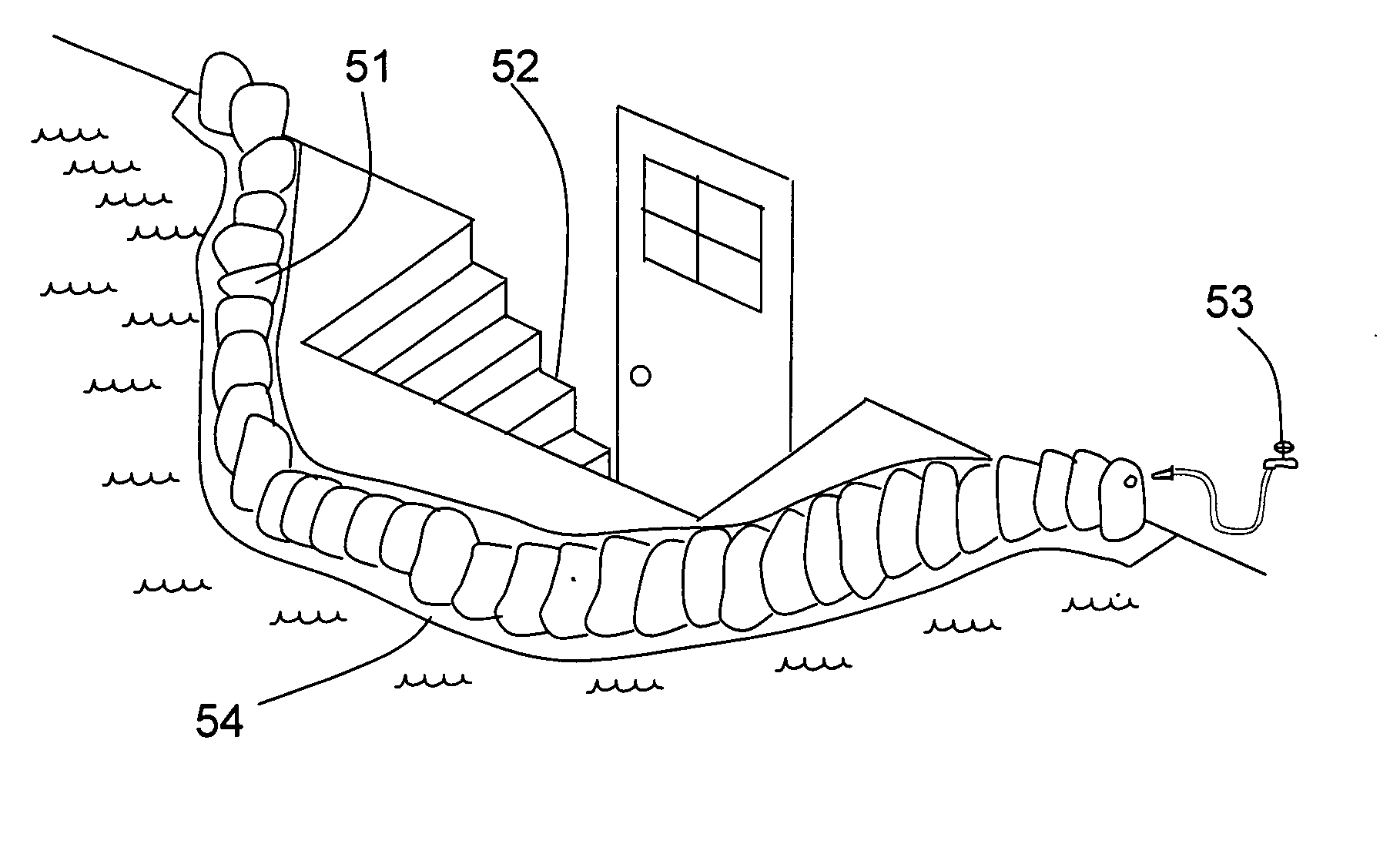
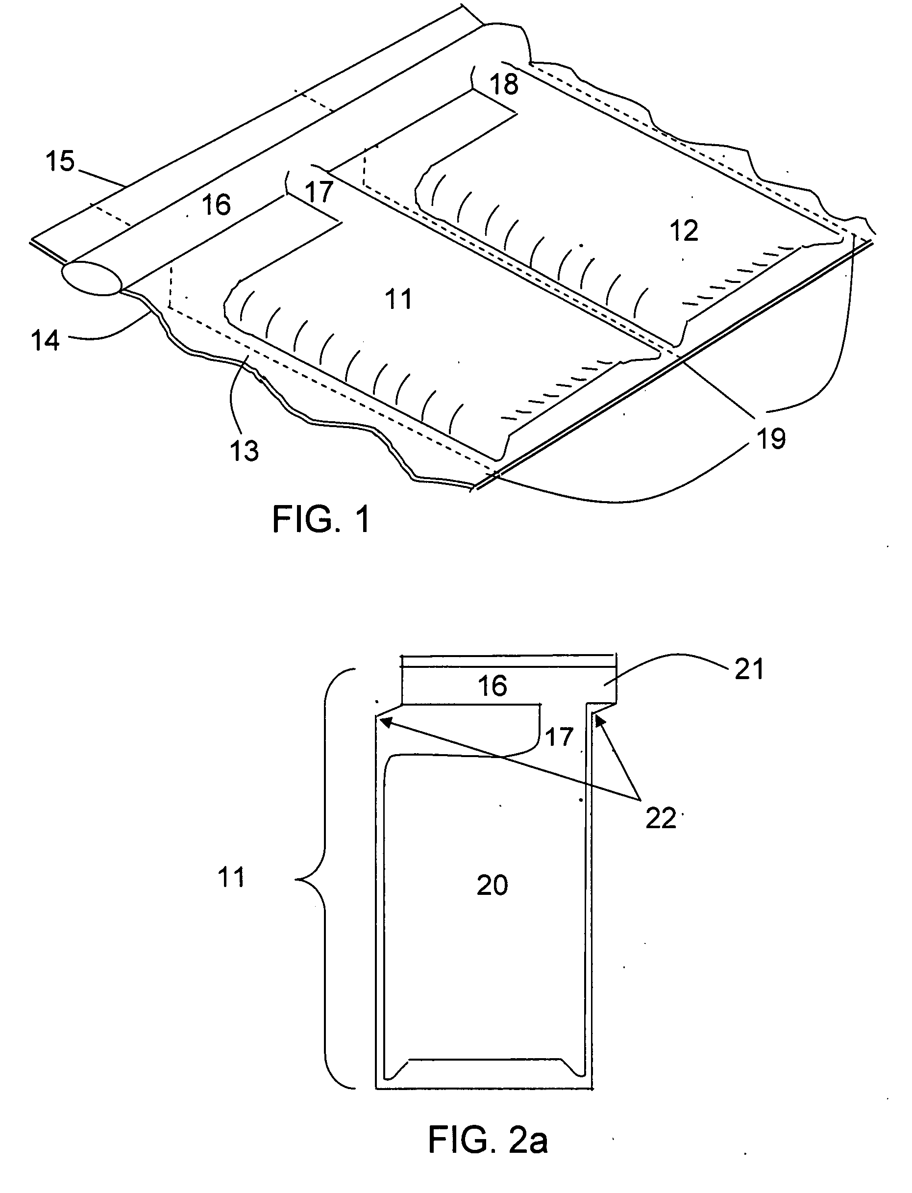
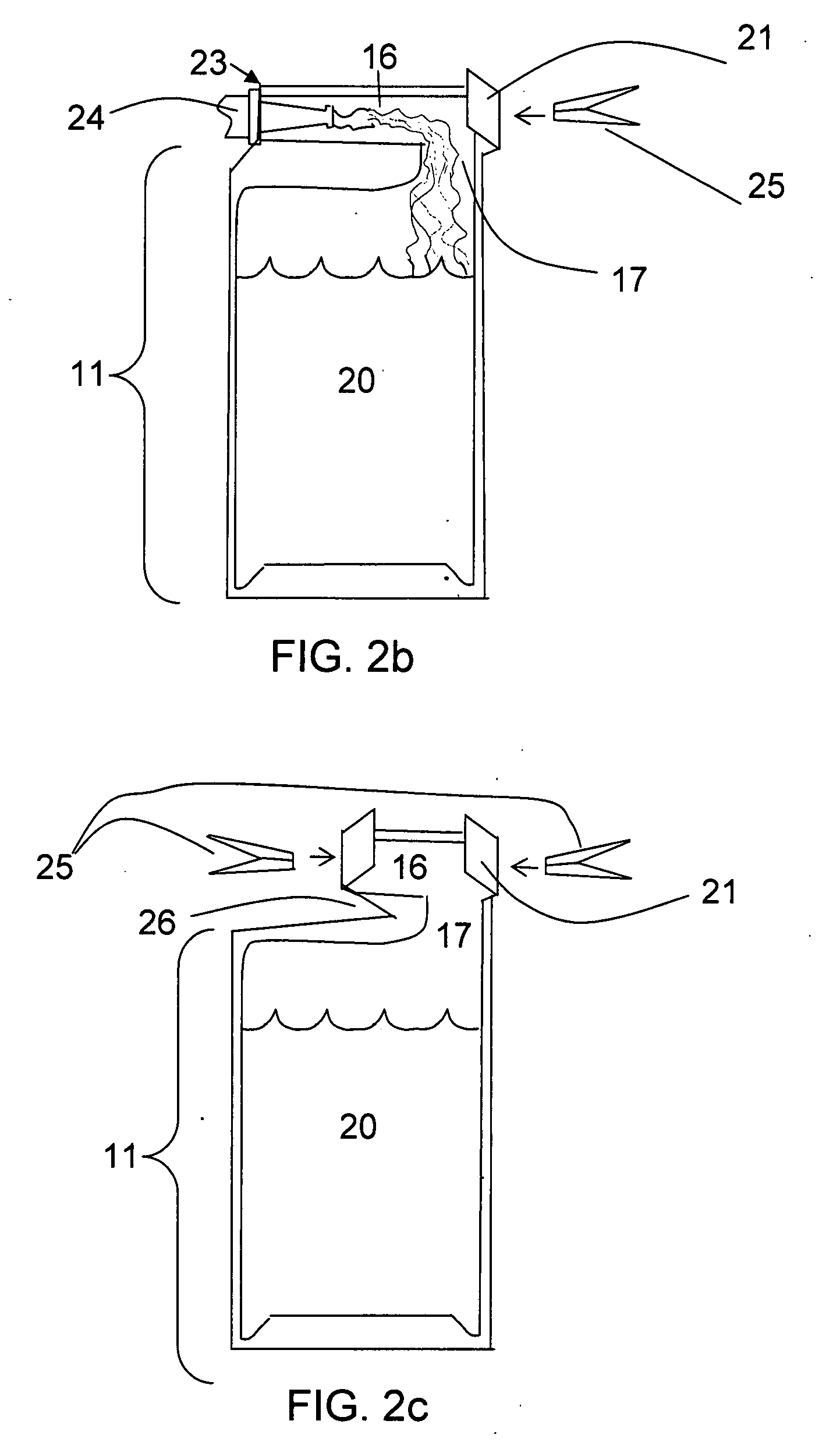
[0056]FIG. 1 illustrates a perspective view of two exemplary hollow chambers or flood bags 11 and 12 that are part of a continuous sheet of such bags, in accordance with an embodiment of the present invention. The present embodiment, Embodiment 1, comprises two flood bags 11 and 12 that are shown as part of a continuous series of such bags that can be wound into a roll or coil or folded similar to an accordion. Flood bags 11 and 12 are formed between two layers 13 and 14 of plastic sheeting. The material anticipated for use is polyethylene but other types of impermeable plastic fabric or sheeting may be substituted such as, but not limited to, rubberized cloth or canvas. Plastic layers 13 and 14 may be separate sheets of plastic or a single sheet of plastic folded along an edge 15 to form layers 13 and 14. The fabric used to form flood bags 11 and 12 is thick enough to be somewhat puncture resistant such as, but not limited to, 10-mil polyethylene sheeting. However, when in use bags...

embodiment 2

[0080]FIG. 11 is an end-view perspective showing how flood bags 91, 92, 93, and 94, as illustrated by way of example in FIG. 9, can be folded to form two rows of tandem flood bags with bags 91 and 92 toward the front and bags 93 and 94 partially obscured to the rear, in accordance with an embodiment of the present invention. This is similar to the method in which two rows of tandem bags are formed in Embodiment 2 as illustrated in FIGS. 6, 7, and 8a, 8b and 8c. However, in the present embodiment, bottom flaps 97a and 97b are sealed to each other longitudinally along a centerline 1110, by a method such as, but not limited to gluing, welding, or stitching, so that each row of flood bags is attached to the other at fill-tube 95 at the top and at centerline 1110 at the bottom. By allowing extra slack in a bottom panel 1120 a connecting membrane is created between the bottoms of flood bags 91, 92, 93 and 94 allowing the bags to spread somewhat apart to form an “A-frame” structure that ca...


PUM


Abstract

An emergency flood control apparatus is described that includes a row of a plurality of vertically separated cells horizontally arranged formed between at least two continuous sheets of impermeable flexible material, a continuous horizontal tube formed between the sheets and disposed at an end of the cells, and a plurality of necks disposed perpendicularly between the tube and the cells, the necks connecting each of the cells to the horizontal tube in a manner such that the cells may be filled with fluid from the tube at substantially the same time.

Description

CROSS-REFERENCE TO RELATED APPLICATIONS[0001]The present Utility patent application claims priority benefit of the [U.S. provisional application for patent Ser. No. 60 / 791,761 filed on Apr. 12, 2006 under 35 U.S.C. 119(e). The contents of this related provisional application are incorporated herein by reference for all purposes.FEDERALLY SPONSORED RESEARCH OR DEVELOPMENT[0002]Not applicable.REFERENCE TO SEQUENCE LISTING, A TABLE, OR A COMPUTER LISTING APPENDIX[0003]Not applicable.COPYRIGHT NOTICE[0004]A portion of the disclosure of this patent document contains material that is subject to copyright protection. The copyright owner has no objection to the facsimile reproduction by anyone of the patent document or patent disclosure as it appears in the Patent and Trademark Office, patent file or records, but otherwise reserves all copyright rights whatsoever.FIELD OF THE INVENTION[0005]The present invention relates to various devices and structures using water or air filled tubes, blad...

Claims


Application Information

Patent Timeline
IPC IPC(8): E02B7/02
CPCE02B3/108E06B9/00E02B3/127
Inventor TYLER, TIM RICHARD
Owner TYLER TIM RICHARD
Why Eureka
Try Eureka