Swiftly adjusting device for a blade shaft of a planer

a technology of adjusting device and blade shaft, which is applied in the direction of metal working apparatus, flat surfacing machines, manufacturing tools, etc., can solve the problems of many times of testing, take a long time for adjusting or taking off the blade shaft, etc., and achieve the effect of minutely and swiftly adjusting

Active Publication Date: 2007-10-25
CHUANG BOR YANN
View PDF3 Cites 10 Cited by
  • Summary
  • Abstract
  • Description
  • Claims
  • Application Information

AI Technical Summary

Benefits of technology

[0006] The feature of the invention is an adjusting hollow space provided in a front portion of a machine body of a planer, an adjusting member movably combined under the bottom of the center of the adjusting hollow space, and an adjusting bearing support pivotally connected to a blade shaft located in a shaft opening in the center portion of the work table fixed on the machine body. The adjusting bearing support is received in the adjusting hollow space, having its bottom contacting the upper end of the adjusting member so that the blade shaft can be minutely and swiftly adjusted in its level to the worktable by screwing up and down the adjusting member in a minute way to move up and down minutely the adjusting bearing support in the adjusting hollow space.

Problems solved by technology

Thus it takes much time for adjusting or taking off the blade shaft 12.
Further, in adjusting the elongate bolts 114, it cannot be seen owing to its low position, requiring many times of testing, quite troublesome.

Method used


Image

  • Swiftly adjusting device for a blade shaft of a planer
  • Swiftly adjusting device for a blade shaft of a planer
  • Swiftly adjusting device for a blade shaft of a planer

Examples


Embodiment Construction

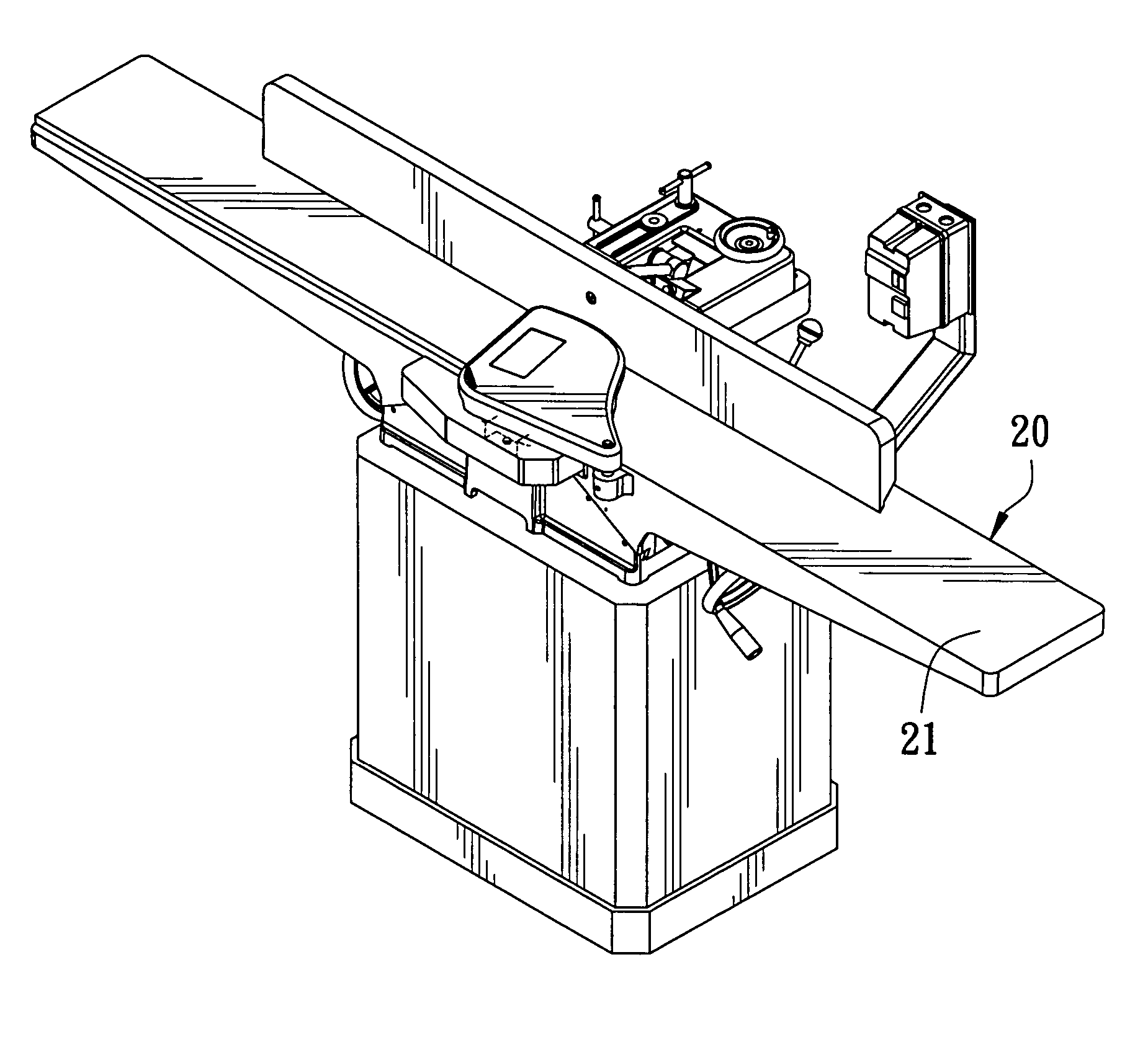
[0015] A preferred embodiment of a swiftly adjusting device for a blade shaft of a planer in the present invention, as shown in FIGS. 3, 4, and 5, includes a blade shaft 30 adjustably combined with a machine body 20.

[0016] The machine body 20 has a worktable 21 fixed on an upper side, and a blade opening 22 is formed in a center portion of the worktable 21, so the blade shaft 30 may be pivotally combined in the blade opening 22.

[0017] The machine body 20 is provided with an adjusting hollow space 23 formed in a location in a front portion facing the blade opening 22, an adjusting member 231 fitted under the bottom of the adjusting hollow space 23. The adjusting member 231 is a bolt and nut engaging an adjusting threaded hole 232 formed in the machine body 20 just under the adjusting hollow space 23. Further, two fixing threaded holes 233 are formed at two sides of the adjusting hollow space 23. The machine body 20 is also provided with a curved recess 24 formed in a rear side and ...


PUM

PropertyMeasurementUnit
distanceaaaaaaaaaa
timeaaaaaaaaaa

Abstract

A swiftly adjusting device for a blade shaft of a planer includes a blade shaft movably positioned in a blade opening of a worktable superposed on a machine body. The machine body has an adjusting hollow space formed in a front portion, and the adjusting hollow space has an adjusting member pivotally connected with a center portion and movable up and down. The blade shaft has an adjusting bearing support pivotally connected to a front end and received in the adjusting hollow space. The bottom of the adjusting bearing support contacts the upper end of the adjusting member so that the blade shaft can be minutely and swiftly adjusted in its level to the worktable by adjusting the adjusting member in a minute way.

Description

BACKGROUND OF THE INVENTION [0001] 1. Field of the Invention [0002] This invention relates to a swiftly adjusting device for a blade shaft of a planer, particularly to one possible to minutely adjust the position of a blade shaft of a manual planer with swiftness. [0003] 2. Description of the Prior Art [0004] A conventional planer shown in FIGS. 1 and 2 includes a body 11, a worktable 11 fixed on the body 11 for placing a work thereon to be planed, a blade shaft 12 positioned in the center opening of the work table 111 and driven by a motor (not shown) to plane the work placed on the worktable 111. The blade shaft 12 is pivotally supported by a bearing fitted in a bearing support 13 respectively at two ends, and the body 11 is provided with a bearing support recess 112 respectively at two sides for receiving the two bearing supports 13. Each bearing support recess 112 has a vertical hole 113 extending from its bottom down in the body 11, and each bearing support 13 has a threaded ho...

Claims


Application Information

Patent Timeline
Patent Type & Authority Applications(United States)
IPC IPC(8): B27B27/06
CPCB27C1/14B27C1/02Y10T83/7697
Inventor CHUANG, BOR-YANN
Owner CHUANG BOR YANN
Why Eureka
Try Eureka