
Image processing apparatus
a technology of image processing apparatus and image, which is applied in the field of image processing apparatus, can solve the problems of insufficient versatility of conventional image processing apparatus, inability to obtain a high-frequency component, and inability to obtain a mixture signal, so as to avoid increased circuit scale
- Summary
- Abstract
- Description
- Claims
- Application Information
AI Technical Summary
Benefits of technology
Problems solved by technology
Method used
Image

Examples
Embodiment Construction
[0041]A preferred embodiment of the present invention will now be described in detail referring to the drawings. In the drawings, the same reference characters indicate the same or corresponding components.
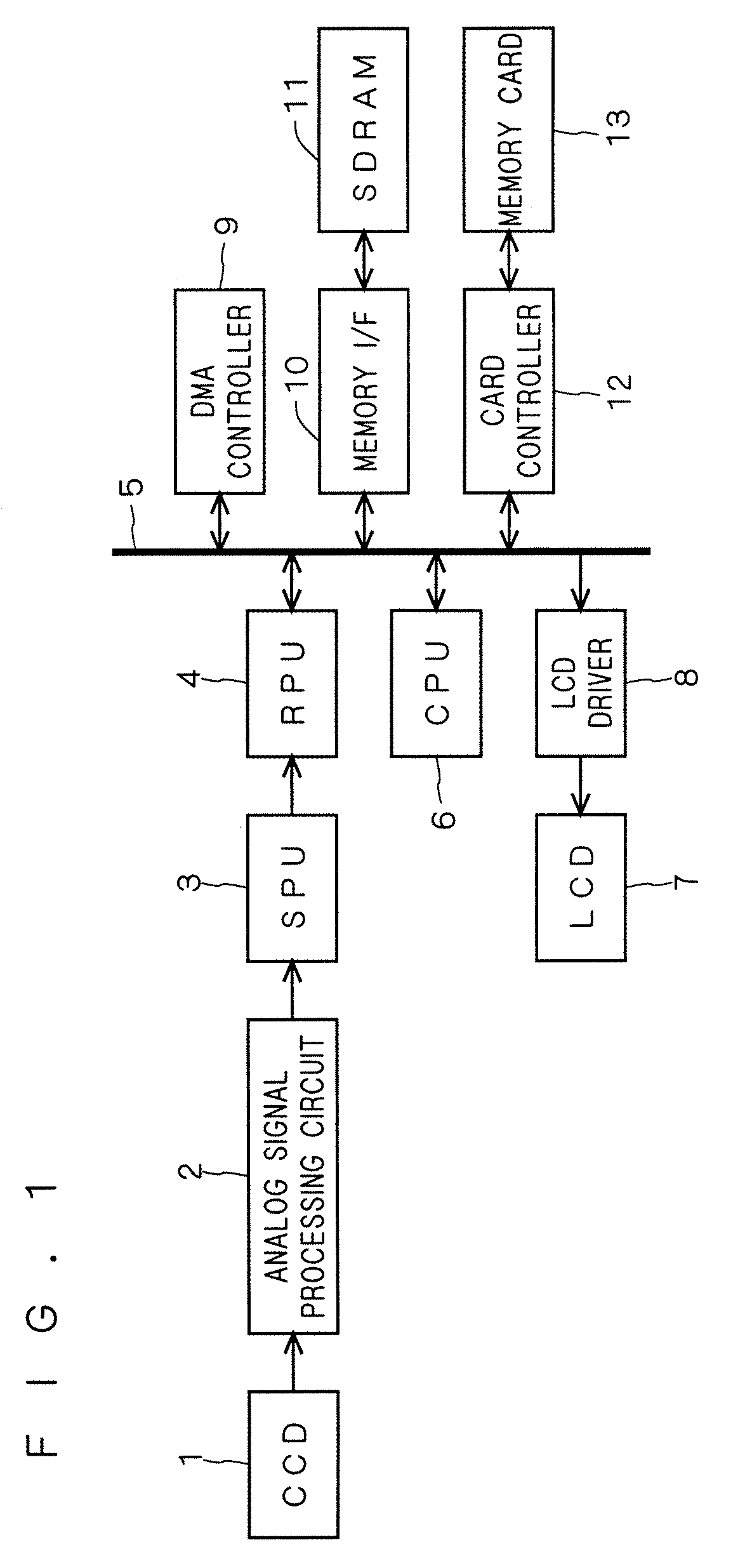
[0042]FIG. 1 is a block diagram schematically illustrating the entire configuration of a digital still camera according to a preferred embodiment of the present invention. A CCD 1 is followed by an analog signal processing circuit 2. The analog signal processing circuit 2 is followed by an SPU (Sensor Processing Unit) 3. The SPU 3 is followed by an RPU (Real-time Processing Unit) 4. The RPU 4 is connected to a main bus 5. As well as the RPU 4, a CPU 6, an LCD driver 8, a DMA controller 9, a memory interface 10, and a card controller 12 are also connected to the main bus 5. An LCD 7 is connected to the LCD driver 8, an SDRAM 11 is connected to the memory interface 10, and a memory card 13 is connected to the card controller 12.
[0043]The CCD 1 has a three-color-system color filter f...
PUM
 Abstract
Description
Claims
Application Information