Method for correcting scanner non-uniformity

a technology of non-uniformity and scanner, which is applied in the field of correcting non-uniformity defects in printed images, can solve the problems of non-uniform appearance, difficult and expensive manufacturing of strips with reflectance variation of 0.1% or less, and the quality of calibration is only as good as the uniformity, so as to reduce the variability, reduce the cost of manufacturing, and reduce the effect of cos

Inactive Publication Date: 2007-10-25
XEROX CORP
View PDF16 Cites 16 Cited by
  • Summary
  • Abstract
  • Description
  • Claims
  • Application Information

AI Technical Summary

Benefits of technology

[0002] In the past, scanners have been made either as moving spot scanners, in which a single sensor and light source sequentially scan in across a page in a fast scan direction, and then advance to a next position in a slow scan direction before scanning again in the fast scan direction; or as full width array scanners, in which a large collection of sensors and one or more light sources simultaneously capture information from an entire line of the page in the Full width array type scanners have more complex electronic devices but simpler electro-mechanical systems. For a given speed, they also have much lower bandwidth requirements at the sensor, and lower light level requirements, such that the sensor obtains enough photons in the time it spends at a given position. For these reasons and others, full width array scanners have become the low cost option in recent years.

Problems solved by technology

This is partially due to sensor noise, (which is not systematic), and partially due to manufacturing variability in the sensors themselves. FIG. 1 shows a schematic of one full width array color scan bar, with the view of the bar from the paper being scanned.
A difficulty with this method is that the quality of the calibration is only as good as the uniformity of the white strip.
Strips with reflectance variation of approximately 1% or less are readily available: strips with reflectance variation of 0.1% or less are very difficult and expensive to manufacture.
Therefore the non-uniformity is over-corrected for red, resulting in an appearance of non-uniformity, even after calibration with a perfectly uniform calibration strip.
Various methods exist of improving the uniformity of the scan bar and calibration strip, however they may be too expensive for common use.

Method used


Image

  • Method for correcting scanner non-uniformity
  • Method for correcting scanner non-uniformity
  • Method for correcting scanner non-uniformity

Examples


Embodiment Construction

[0023] In the following detailed description, reference is made to the accompanying drawings, which form a part hereof, and in which is shown by way of illustration specific illustrative embodiments in which the invention may be practiced. These embodiments are described in sufficient detail to enable those skilled in the art to practice the invention, and it is to be understood that other embodiments may be utilized and that logical, mechanical and electrical changes may be made without departing from the scope of the disclosure. The following detailed description is, therefore, not to be taken in a limiting sense.

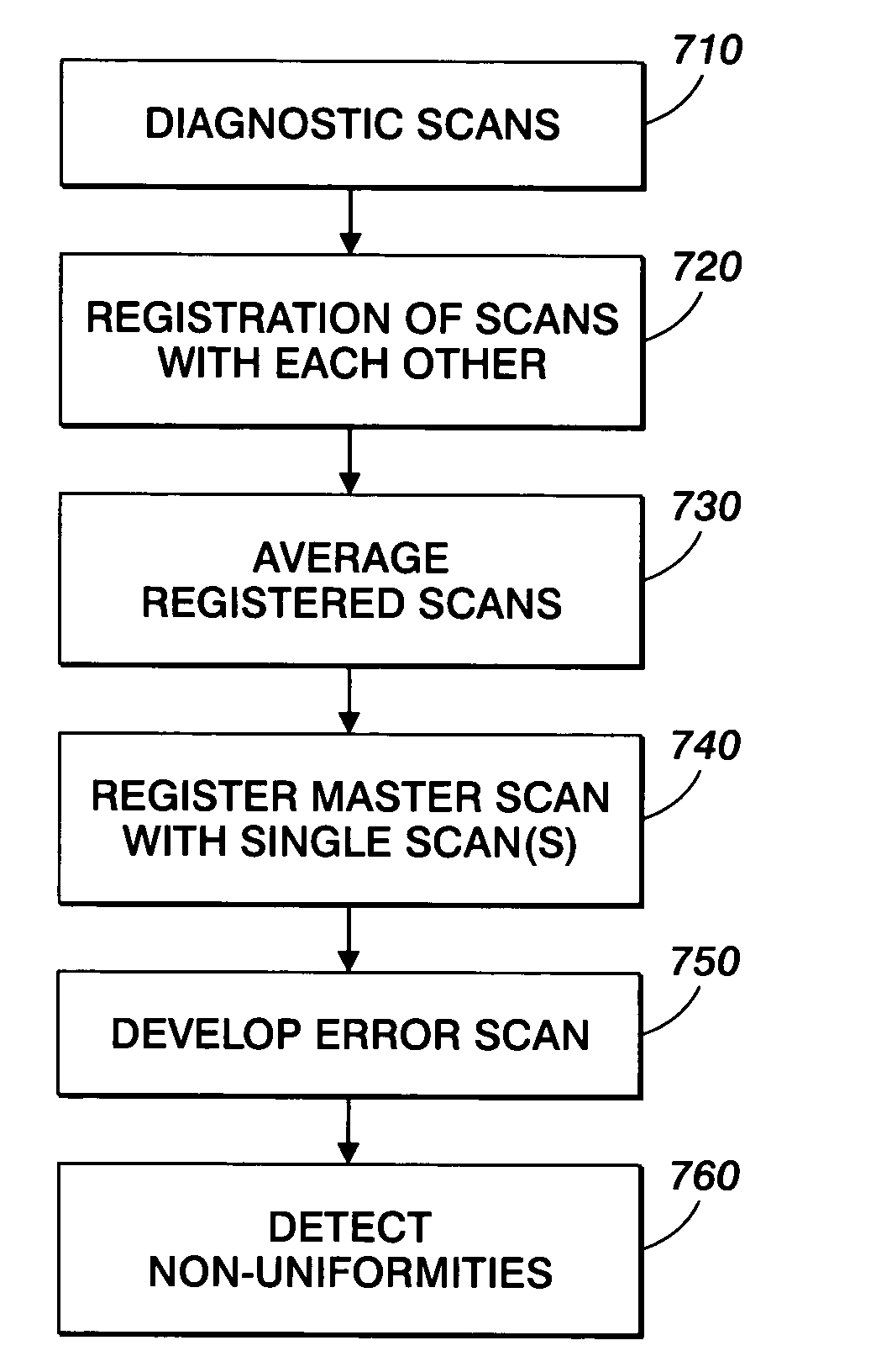
[0024] The method of correcting for scanner non-uniformity as described herein uses approximately uniform pages and the scanner itself to characterize their non-uniformity rather than assuming perfect uniformity of the test pages. The pages are scanned in multiple orientations and translations, each, so that any within-page non-uniformity may be separated from scanner no...


PUM


Abstract

A method for identifying and correcting for spatial variation within scanning bars includes performing diagnostic scans of at least one sheet, in which a sheet(s) is scanned in various orientations and translations, with each of the orientations identified. The diagnostic scans are registered with one of the individual diagnostic scans to produce registered scans. The registered scans are averaged to create a master scan corresponding to the sheet, such that the master scan is indicative of the spatial variation within the sheet.

Description

BACKGROUND AND SUMMARY [0001] This disclosure relates generally to correcting non-uniformity defects in a printed image, and more particularly to a method of correcting for spatial variation within scanning bars. [0002] In the past, scanners have been made either as moving spot scanners, in which a single sensor and light source sequentially scan in across a page in a fast scan direction, and then advance to a next position in a slow scan direction before scanning again in the fast scan direction; or as full width array scanners, in which a large collection of sensors and one or more light sources simultaneously capture information from an entire line of the page in the Full width array type scanners have more complex electronic devices but simpler electro-mechanical systems. For a given speed, they also have much lower bandwidth requirements at the sensor, and lower light level requirements, such that the sensor obtains enough photons in the time it spends at a given position. For ...

Claims


Application Information

Patent Timeline
Patent Type & Authority Applications(United States)
IPC IPC(8): H04N1/46
CPCH04N1/00002H04N1/00018H04N1/00023H04N1/00031H04N1/00045H04N1/486H04N1/00063H04N1/00068H04N1/00087H04N1/193H04N1/401H04N1/00053
Inventor KLASSEN, R. VICTOR
Owner XEROX CORP
Why Eureka
Try Eureka