Twin bifurcated stent graft

Active Publication Date: 2007-10-25
COOK MEDICAL TECH LLC +1
View PDF100 Cites 120 Cited by
  • Summary
  • Abstract
  • Description
  • Claims
  • Application Information

AI Technical Summary

Benefits of technology

[0031] Preferably the valve arrangement comprises a sleeve of a biocompatible graft material within the tubular body and a self expanding stent within the sleeve, the sleeve being fastened at its proximal end to the first leg proximal

Problems solved by technology

There can be problems, however, if the aneurysm of the ao

Method used


Image

  • Twin bifurcated stent graft
  • Twin bifurcated stent graft
  • Twin bifurcated stent graft

Examples


Embodiment Construction

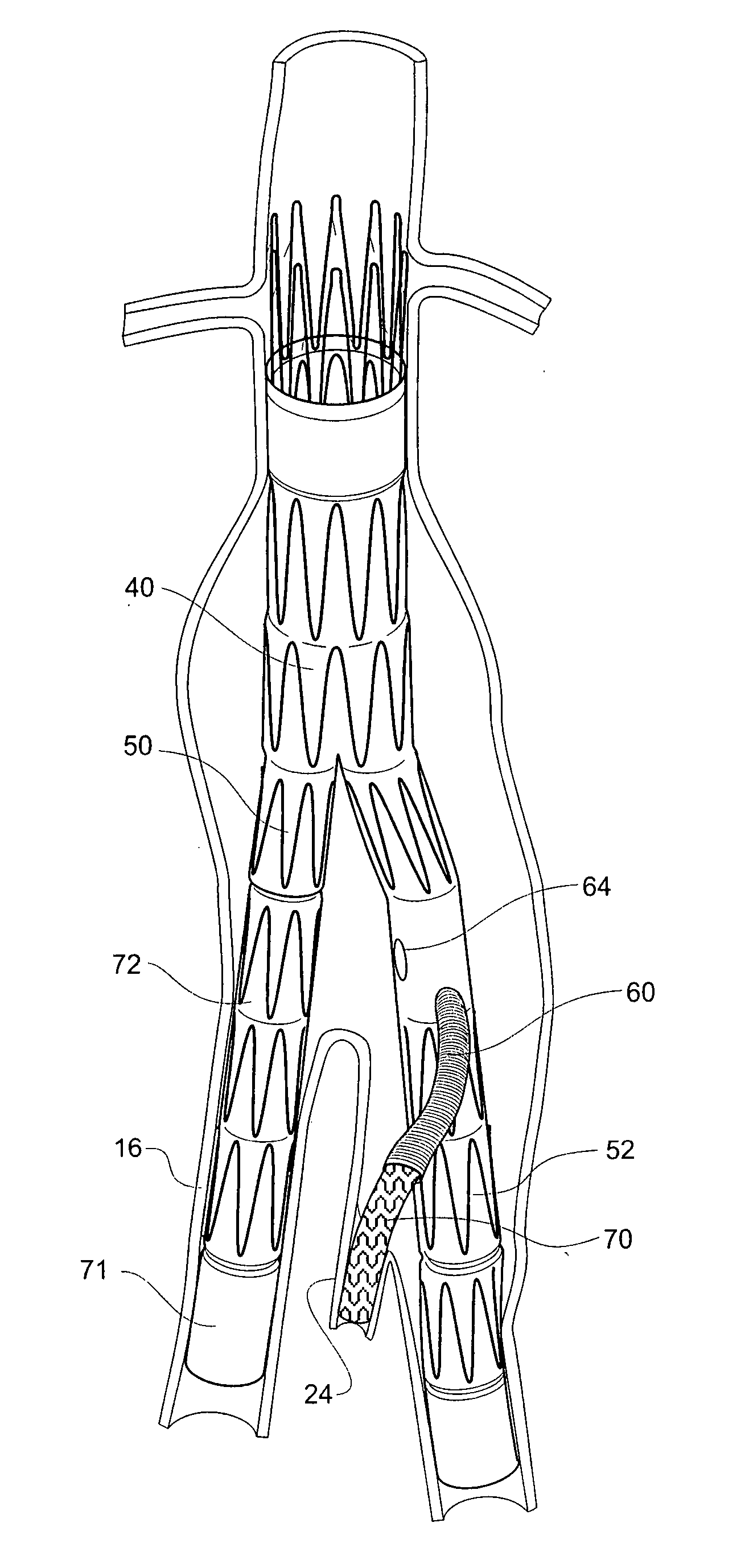
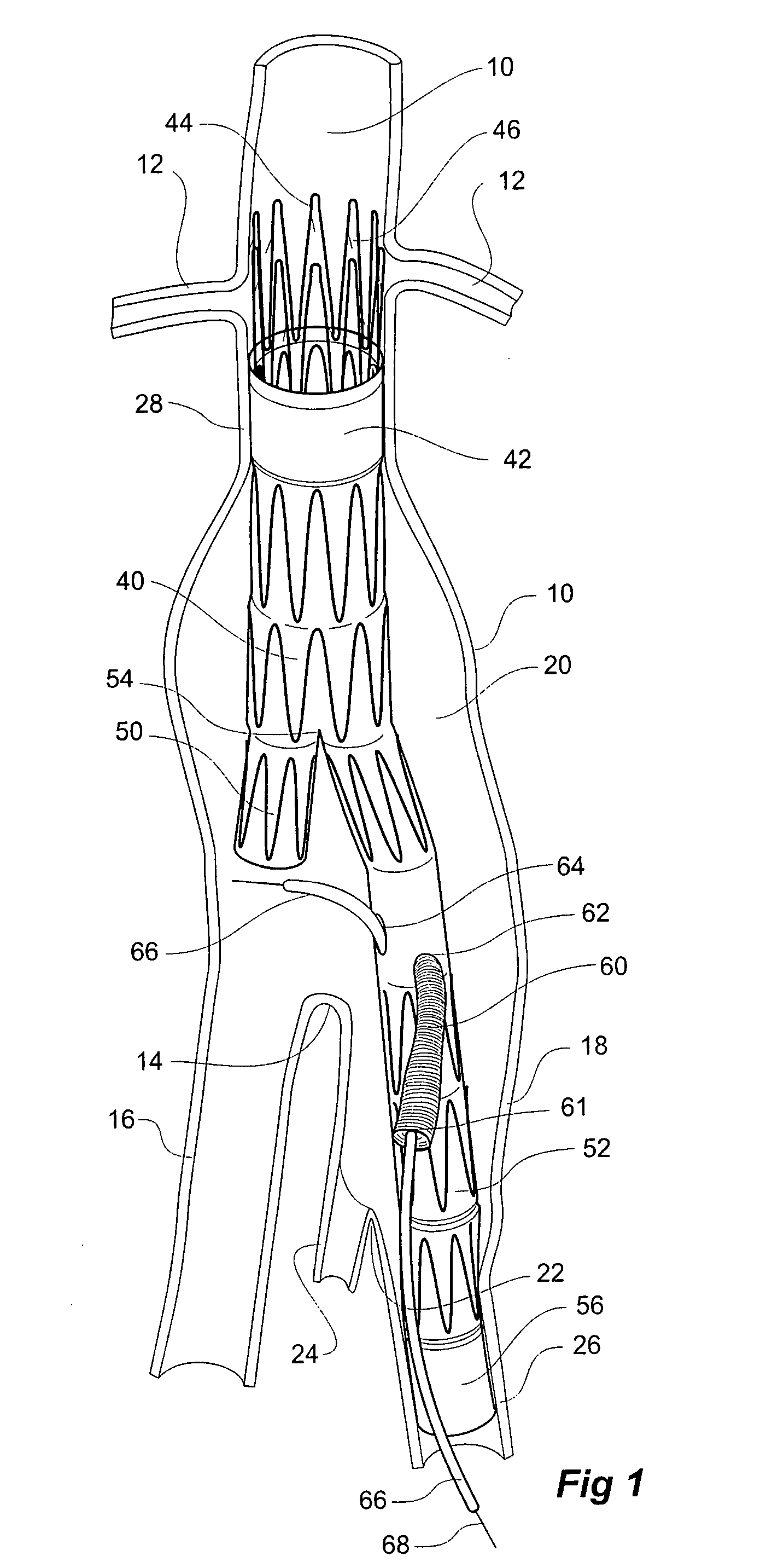
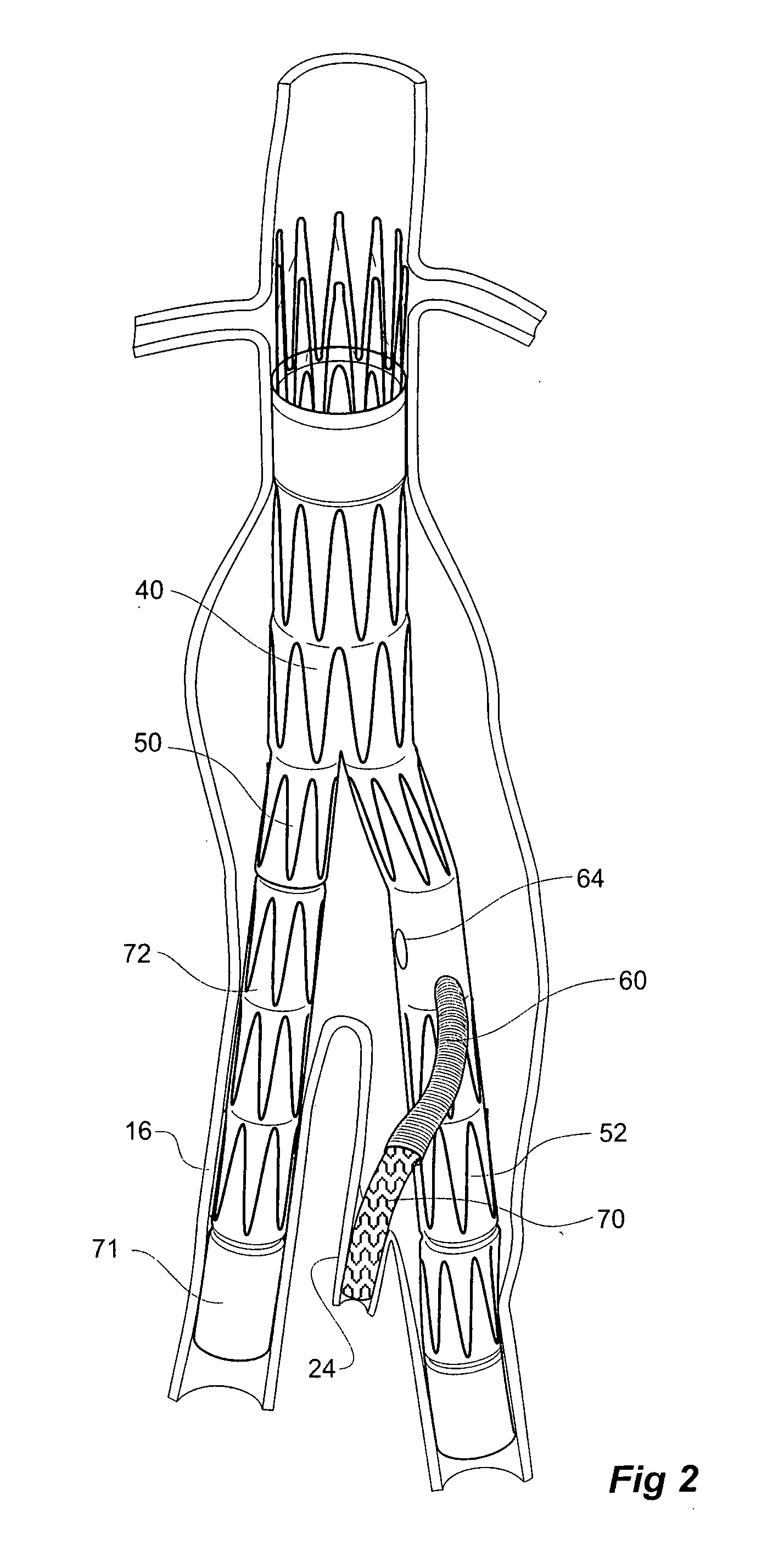
[0053] Looking more closely at the drawings and in particular FIGS. 1 and 2 it will be seen that a schematic view of part of the vascular arrangement of a patient is illustrated incorporating a stent graft according to the present invention.

[0054] The vasculature comprises an aorta 10 in the region between the renal arteries 12 and the aortic bifurcation 14. Common iliac arteries 16 and 18 extend down from the aortic bifurcation 14. The aorta 10 has an aneurysm 20 which extends down into the common iliac artery 18 as far as the bifurcation 22 between the internal iliac artery 24 and the external iliac artery 26.

[0055] To traverse the aneurysm 20 a twin bifurcated aortic stent graft 40 according to one embodiment of the present invention has been deployed into the aorta 10. In this drawing the introduction device which is used to deploy the stent graft into the vasculature has been omitted to assist clarity. In our earlier patent application, PCT Patent Publication No. WO 98 / 53761 ...


PUM


Abstract

A stent graft (40) has a tubular body with a first bifurcation (54) with first and second legs (50, 52) extending from the bifurcation. One of the legs (52) has a further bifurcation (62) to define a side arm. The stent graft can be deployed into the vasculature of a patient with the tubular body being in an aorta of the patient, a first leg extending down an iliac artery, a second leg being directed towards a contralateral iliac artery and the side arm directed to an internal artery of one of the iliac arteries. One of the legs can include a valved aperture to enable the placement of an indwelling catheter therethrough

Description

CROSS-REFERENCE TO RELATED APPLICATIONS [0001] The present application claims priority from U.S. Provisional Patent Application Ser. No. 60 / 793,282 filed Apr. 19, 2006 entitled “TWIN BIFURCATED STENT GRAFT”. The entire content of this application is hereby incorporated by reference.INCORPORATION BY REFERENCE [0002] The following co-pending patent applications are referred to in the following description: [0003] U.S. patent application Ser. No. 10 / 962,763 entitled “Introducer for Iliac Side Branch Device”, filed Oct. 12, 2004, and published Aug. 15, 2005 as U.S. Patent Application Publication No. US-2005-0182476-A1; [0004] PCT Patent Publication No. WO 98 / 53761 entitled “A Prosthesis and a Method of Deploying a Prosthesis”; [0005] U.S. patent application Ser. No. 11 / 600,655 entitled “Stent Graft Introducer”, filed Nov. 16, 2006; [0006] U.S. patent application Ser. No. 11 / 231,621 entitled “Side Branch Stent Graft”, filed Sep. 21, 2005, and published May 4, 2006 as U.S. Patent Applicat...

Claims


Application Information

Patent Timeline
IPC IPC(8): A61F2/06
CPCA61B2017/00243A61F2/07A61F2/24A61F2/954A61F2220/0075A61F2002/067A61F2002/075A61F2/89A61F2002/061A61F2220/0016A61F2/2476A61B17/00234A61F2002/065
Inventor GREENBERG, ROY K.HARTLEY, DAVID ERNESTLAWRENCE-BROWN, MICHAEL
Owner COOK MEDICAL TECH LLC
Why Eureka
Try Eureka