Modular valve assembly

a module and valve assembly technology, applied in the direction of mechanical equipment, functional valve types, transportation and packaging, etc., can solve the problems of large footprint of the sprayer system, time-consuming, complicated and costly assembly,

Active Publication Date: 2018-02-15
VICTAULIC
View PDF14 Cites 14 Cited by
  • Summary
  • Abstract
  • Description
  • Claims
  • Application Information

AI Technical Summary

Benefits of technology

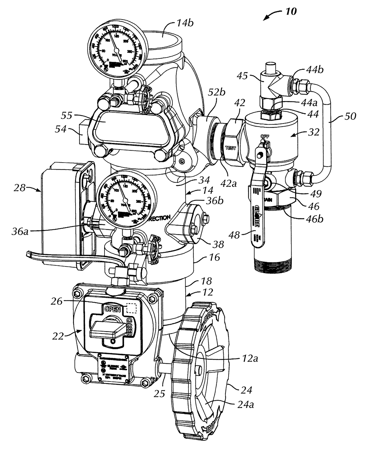
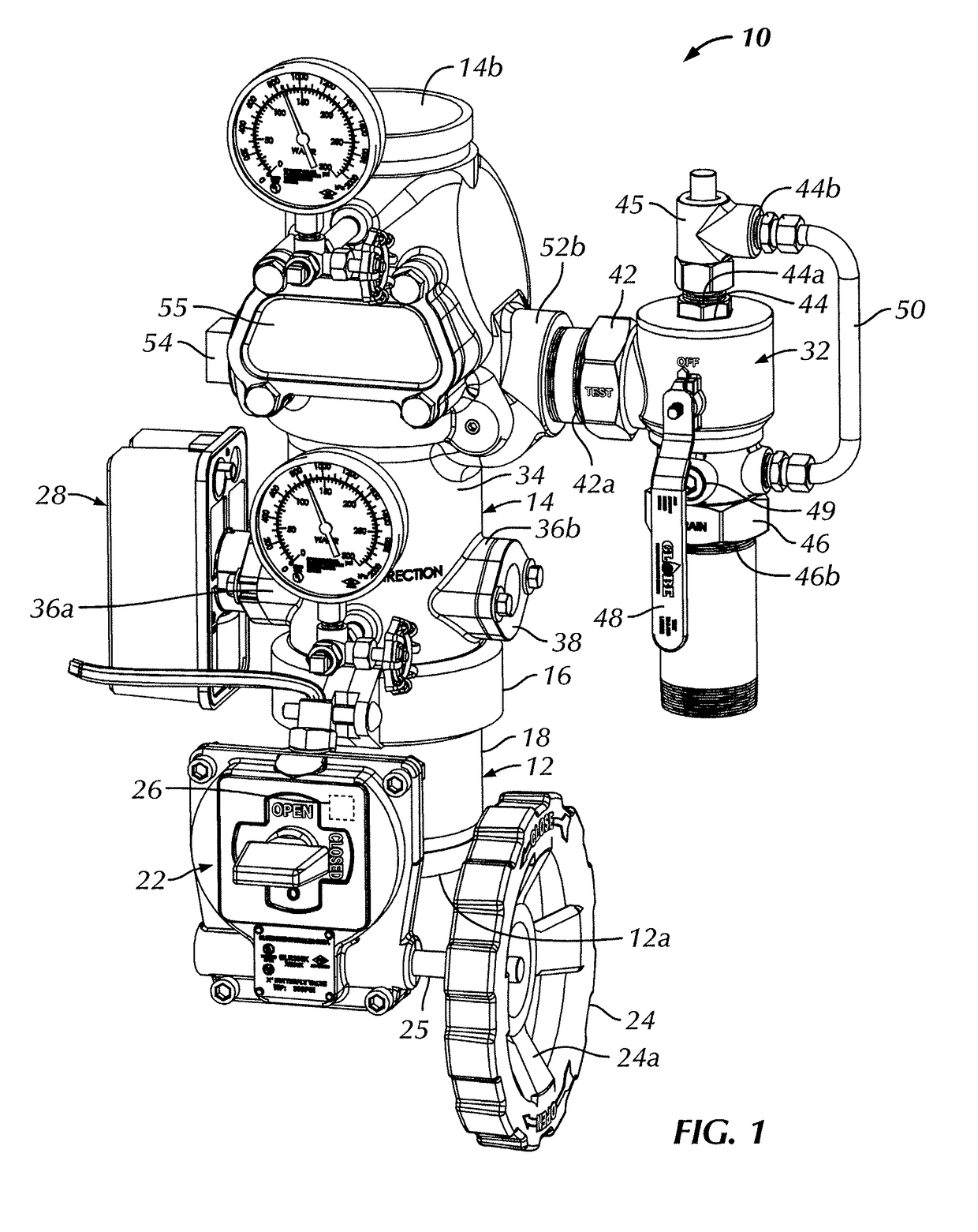
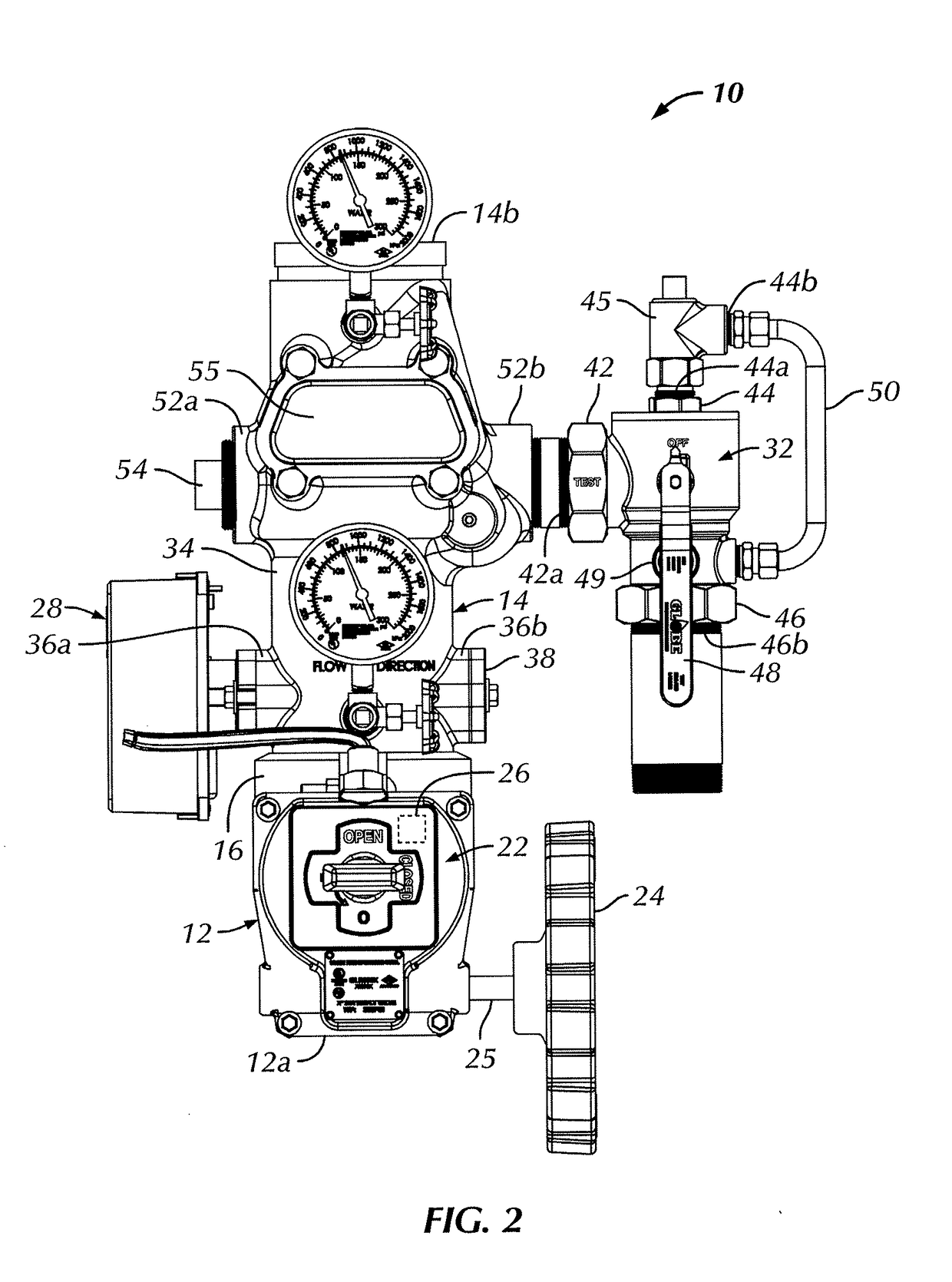
[0007]Another aspect of the present invention is directed to a wet piping system modular valve assembly comprising a single piece valve body having a control valve within the valve body. The control valve has a selectively rotatable control arm operatively coupled therewith to move the control valve between an open position, permitting fluid flow across the control valve, and a closed position, substantially preventing fluid flow across the control valve. A drain valve is removably mounted to the valve body and fluidly connected with the valve body downstream of the control valve. A mechanically independent flow detection switch is removably mounted to the valve body and fluidly connected with the valve body upstream of the drain valve.

Problems solved by technology

Consequently, the manifold of piping of the sprinkler system has a relatively large footprint, is costly to manufacture and is both time consuming, complicated and costly to assemble.

Method used


Image

  • Modular valve assembly
  • Modular valve assembly
  • Modular valve assembly

Examples


Embodiment Construction

[0023]Certain terminology is used in the following description for convenience only and is not limiting. The words “lower,”“bottom,”“upper” and “top” designate directions in the drawings to which reference is made. The words “inwardly,”“outwardly,”“upwardly” and “downwardly” refer to directions toward and away from, respectively, the geometric center of the control valve assembly, and designated parts thereof, in accordance with the present disclosure. Unless specifically set forth herein, the terms “a,”“an” and “the” are not limited to one element, but instead should be read as meaning “at least one.” The terminology includes the words noted above, derivatives thereof and words of similar import.

[0024]It should also be understood that the terms “about,”“approximately,”“generally,”“substantially” and like terms, used herein when referring to a dimension or characteristic of a component of the invention, indicate that the described dimension / characteristic is not a strict boundary or...


PUM


Abstract

A wet piping system modular valve assembly includes a single piece valve body with a check valve within the valve body. The check valve is movable between a closed position and an open position according to a pressure differential across the check valve. A drain valve is removably mounted to the valve body and fluidly connected with the valve body downstream of the check valve. A mechanically independent flow detection switch is removably mounted to the valve body and fluidly connected with the valve body upstream of the drain valve.

Description

CROSS-REFERENCE TO RELATED APPLICATIONS[0001]This application claims priority from U.S. Provisional Patent Application No. 62 / 373,626, titled “Modular Control Valve Assembly”, filed on Aug. 11, 2016, the entire contents of which are incorporated by reference herein.BACKGROUND OF THE INVENTION[0002]The present invention is generally directed to a fluid flow valve assembly, and more particularly to a valve assembly for a sprinkler wet standpipe used to monitor and optionally control water released to downstream sprinklers of a fire suppression sprinkler system.[0003]Fire suppression sprinkler systems designed for protection of commercial and non-commercial properties include some combination or all of a control valve, a check valve, a water flow detection switch, a test valve, a drain valve and a pressure relief valve. A control valve is utilized to allow water flow to the sprinklers downstream thereof to be shut off, e.g., for maintenance purposes. A check valve retains fluid and pre...

Claims


Application Information

Patent Timeline
Patent Type & Authority Applications(United States)
IPC IPC(8): A62C35/68A62C35/60
CPCA62C35/60A62C35/68A62C35/605F16K37/005F16K1/22F16K15/033F16K17/048Y10T137/8326
Inventor RINGER, YORAMMAUGHAN, KEVIN DESMONDARCHIBALD, THOMAS EDWINMEYER, STEPHEN J.
Owner VICTAULIC
Why Eureka
Try Eureka