
Fluid metering valve

Active Publication Date: 2005-07-14
WOODWARD GOVERNOR CO
View PDF8 Cites 14 Cited by
  • Summary
  • Abstract
  • Description
  • Claims
  • Application Information

AI Technical Summary

Benefits of technology

[0006] Another aspect of the present invention is directed toward a fluid metering valve assembly for integrally shutting off and metering fluid flow in response to an electrical demand input. Thus, both shutoff and metering functions can be performed by a single valve. According to this aspect, the fluid metering valve assembly includes a valve housing including a fluid inlet, a metered fluid outlet, a flow passageway between the metered flow outlet and the fluid inlet, and a valve seat disposed along the flow passageway. A valve member is disposed along the flow passageway and is moveable toward and away from the valve seat. An electrical actuator moves the valve between a fully closed position in which the valve member is seated against the valve seat and an open position in which the valve member is spaced from the valve seat. An elastomeric seal between the valve member and a valve seat when the valve is in the fully closed position provides a seal and prevents fluid flow from the inlet to the metered flow outlet, thereby enabling a shutoff function. The electrical actuator positions the valve member in a predetermined position in response to a demand input to set a fluid flow rate of fluid through the metered flow output thereby enabling a metering function in the same valve.
[0007] With respect to this aspect, and according to one of the embodiments of the present invention, two separate valve portions may be provided along the valve stem including a closure portion and a metering portion. According to this embodiment, the valve housing further includes a nozzle section in spaced relation to the valve seat which provides a restriction orifice in combination with the metering portion in order to meter fluid flow. The closure portion seals against the valve seat to prevent flow portion through the nozzle section. Thus, a single actuator is effectively controlling the size of two different restrictions provided by two different valve plugging portions along a valve in the valve assembly.
[0008] An additional aspect of the present invention is directed toward a mechanism for stopping the valve assembly at or near the fully closed position. According to this aspect, the valve assembly also includes a valve housing defining a flow passageway and a valve member arranged along the flow passageway for regulating flow therethrough. A valve stem similarly extends from the valve member. Between an actuator which provides an output on a motor shaft and the valve stem is a gear assembly comprising an output gear, a sector gear, and an input gear which acts upon the valve stem. The sector gear is rotatable relative to a pivot and has a first gear section engaging the output gear (thereby being driven by the motor) and a second gear section engaging the input gear. A first stop structure is provided integral with the shaft of the actuator and a second stop structure is provided integral with the sector gear. The first and second stop structures engage each other at a position proximate a fully closed position of the valve member. One application and / or advantage of this design is that it may be used to establish a home position in the event of power loss to the actuator. In an embodiment and application, spring and / or fluid forces would tend to fully close the valve which could in turn want to cause the system to over rotate and thereby could prevent the establishment of a home position or reference point upon reestablishing power. By having a known predetermined home position, by virtue of the first and second stop structures, the potential adverse effects of power loss are eliminated or otherwise minimized.

Problems solved by technology

However, when the actuator drives the output gear in a second direction, the actuator may not necessarily drive the valve member due to the slidable disposition of the input gear on the valve stem.

Method used


Image

  • Fluid metering valve
  • Fluid metering valve
  • Fluid metering valve

Examples


Embodiment Construction

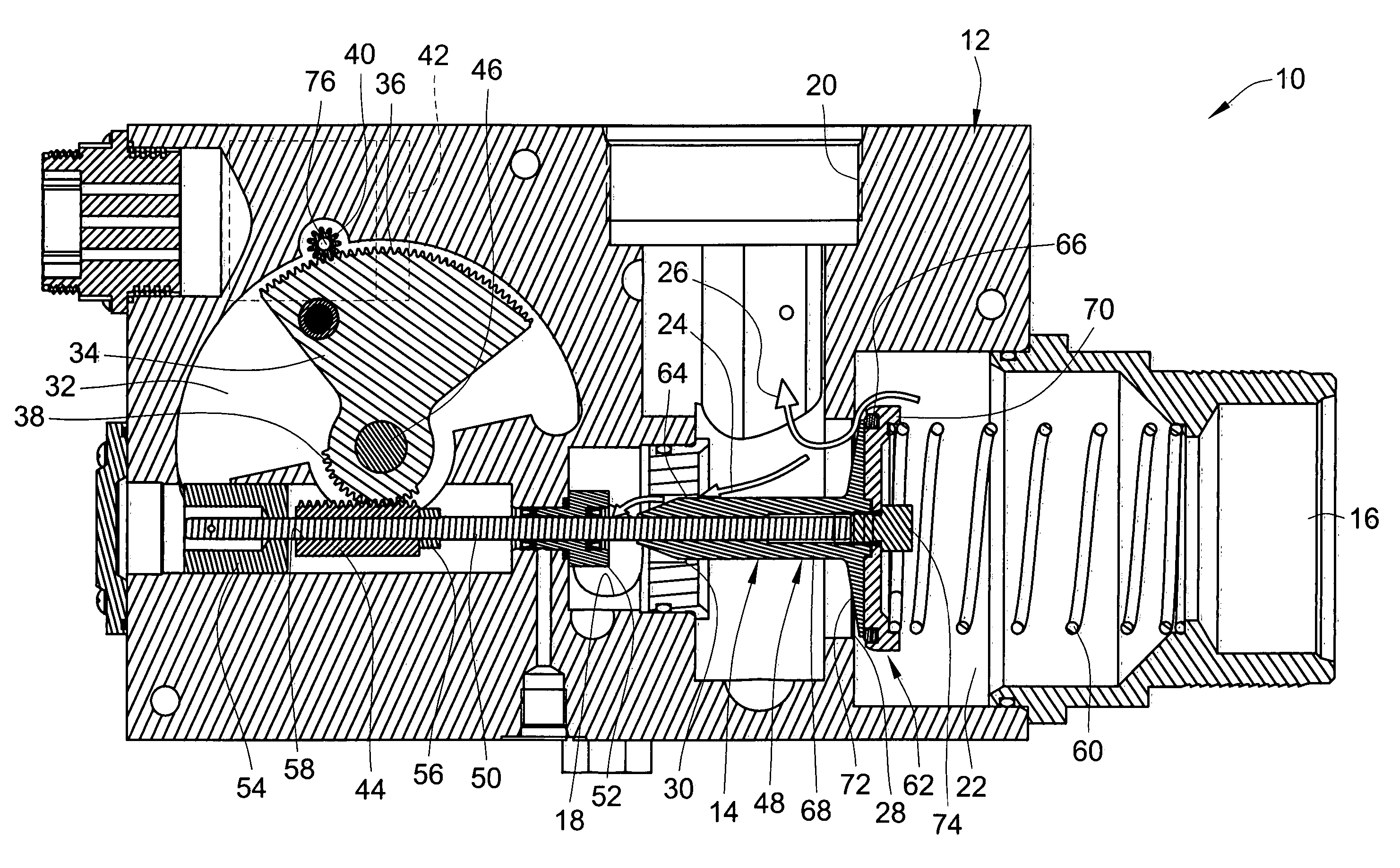
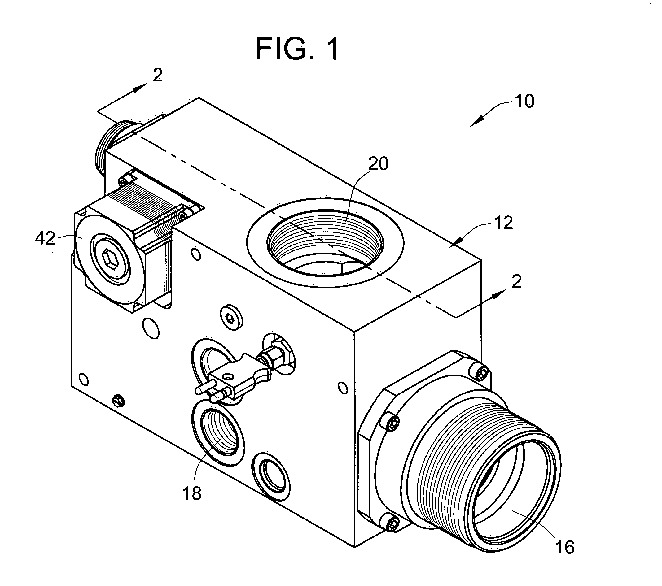
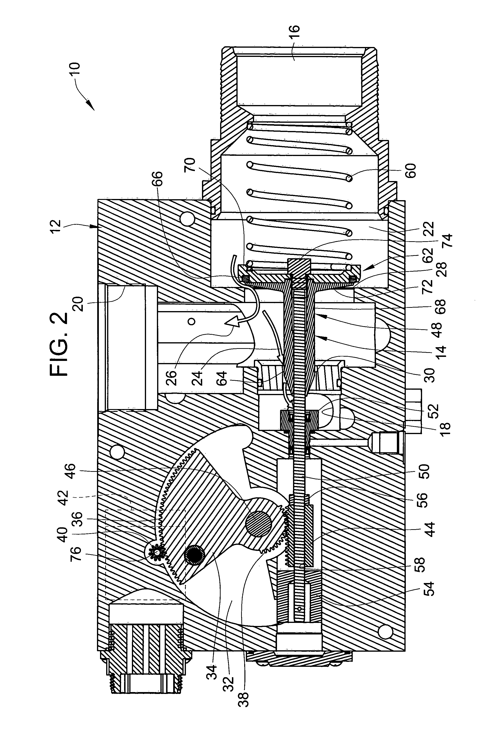
[0019] Referring to FIGS. 1 and 2, an embodiment of a fluid metering valve assembly 10 is shown in accordance with a first embodiment of the present invention. The valve assembly 10 generally includes a valve housing 12 that provides for various ports and passageways and which also slidably supports a movable valve member 14 therein. In the first embodiment, the valve housing 12 provides an inlet port 16 for receiving fluid and two outlet ports including a metered flow outlet port 18 and a main flow or unmetered flow outlet port 20. Between and among the various ports 16, 18 and 20, there is provided an internal flow passageway 22 to provide a first flow path 24 from the inlet port 16 to the metered flow outlet port 18 and a second flow path 26 from the inlet port 16 to the unmetered flow outlet port 20.

[0020] Along the flow passageway 22, the valve housing 12 also provides a valve seat 28 fluidically between the inlet port 16 and each of the outlet ports 18 and 20, and a metering ...


PUM


Abstract

A fluid metering valve includes a gear rack which is slidable on a valve stem in which a spring counteracts the force of an actuator to maintain a constant load on the gear mechanism to prevent backlash. Corresponding stop mechanisms between the gear and the shaft of a rotary actuator come into engagement with each other near a fully closed position of the fluid metering valve for zero calibration purposes upon power loss to the actuator. A single valve member and a single actuator of the fluid metering valve provides for both a shut-off function and a metering function.

Description

FIELD OF THE INVENTION [0001] The present invention relates generally to fluid metering valves and more particularly relates to gear mechanisms and / or shutoff mechanisms for fluid metering valves. BACKGROUND OF THE INVENTION [0002] There are a wide variety of different types of applications where fluid metering valves are used for controlling the flow rate of gas or liquid in a fluid system, such as in an engine. One application where there is anticipated to be a significant need is fluid metering valves for controlling the flow rate of natural gas and air into various fuel cell prime movers. Fuel cell technology is currently very promising. In fuel cell applications, there is a need for a highly accurate and low cost fluid metering system to control the flow rate of natural gas and air into various fuel cell prime movers. Other such applications outside the fuel cell technology may also benefit from such a highly accurate and low cost fluid metering system. The present invention is...

Claims


Application Information

Patent Timeline
IPC IPC(8): F16K31/04F16K31/54
CPCF16K31/54F16K31/047
Inventor BRINKS, BARRY T.WOLVERTON, DANA NOVA JOYCECANNON, DELBERT DWIGHTMCDANIEL, GARY F.
Owner WOODWARD GOVERNOR CO
Learn More