Catheter with autoinflating, autoregulating balloon

a technology of auto-inflating and auto-regulating balloons, which is applied in the field of catheter assemblies, can solve the problems of inability to fully fully fully utilize the auto-inflating catheter balloon assemblies, the balloon design may not be suitable for use, and the balloon is not suitable for auto-inflating catheters

Inactive Publication Date: 2011-03-22
MEDTRONIC INC
View PDF35 Cites 14 Cited by
  • Summary
  • Abstract
  • Description
  • Claims
  • Application Information

AI Technical Summary

Benefits of technology

[0012]In one embodiment, the fluid discharge aperture is formed in a fluid flow channel provided in the catheter body adjacent to the balloon. The outer end of the fluid flow channel opens to the exterior of the catheter body. The autoregulation valve comprises an inner end of the fluid flow channel and a portion of the balloon surrounding the inner end of the fluid flow channel so that fluid inside the lumen is prevented from entering the fluid flow channel for discharge from the assembly when the balloon is in the relaxed, uninflated state. The balloon is expandable in response to an increase in fluid pressure in the lumen above the pressure on the exterior of the balloon. Above a predetermined differential, the inner end of the fluid flow channel opens to the interior of the balloon to discharge fluid from the lumen by way of the interior of the balloon and the fluid flow channel.

Problems solved by technology

Prior balloon designs may present, one or more of several problems.
Therefore, the balloon is difficult to insert into the coronary sinus and may cause trauma to the tissue as it is inserted.
Heretofore, however, tightly fitting elastomeric balloons have not been employed in autoinflating catheter balloon assemblies because no effective means were known for controlling the inflation rate of the elastomeric balloon.

Method used


Image

  • Catheter with autoinflating, autoregulating balloon
  • Catheter with autoinflating, autoregulating balloon
  • Catheter with autoinflating, autoregulating balloon

Examples


first embodiment

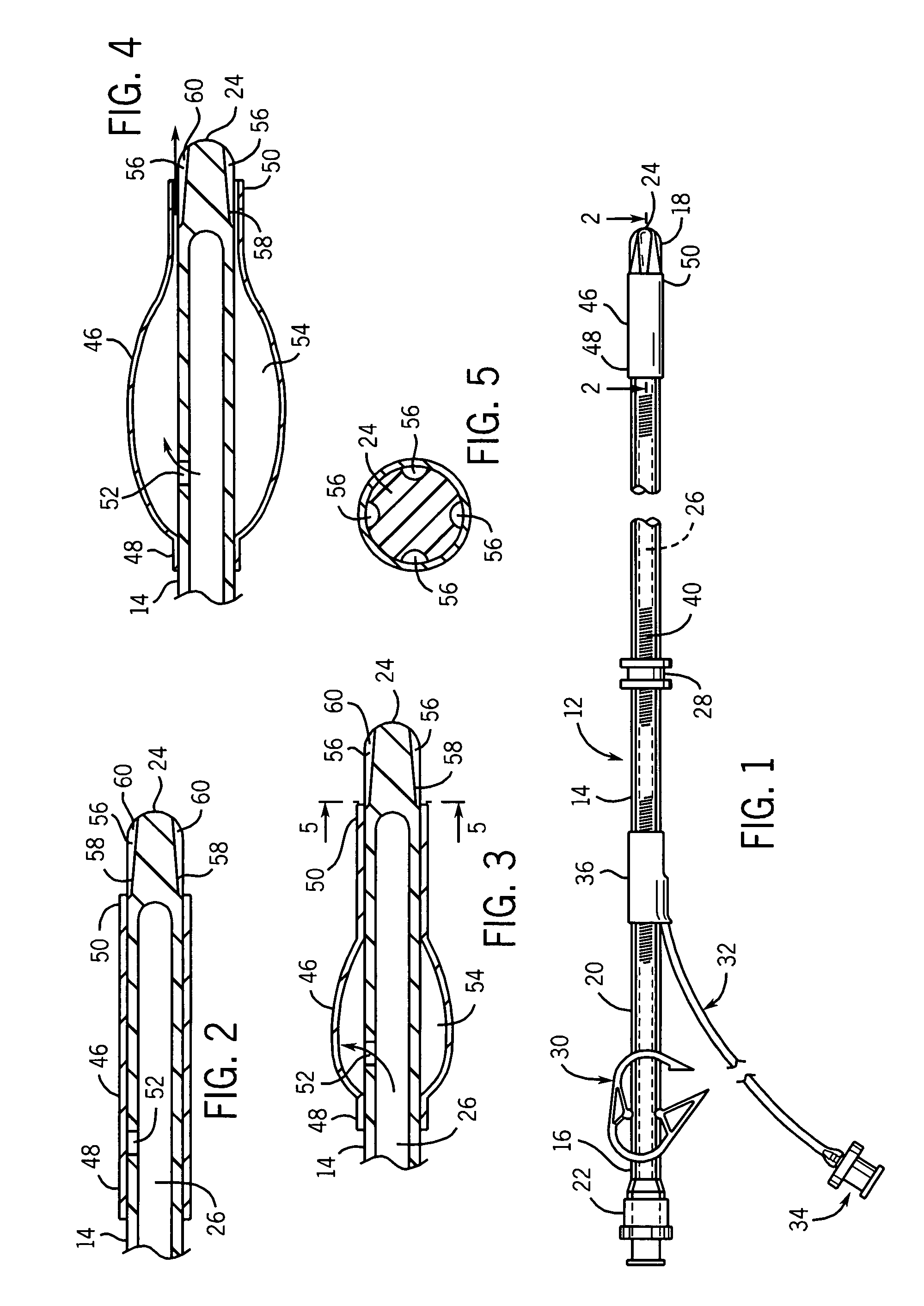
[0035]Referring now to the drawings and to FIG. 1 in particular, a catheter assembly 12 according to the invention is shown. In this embodiment, the catheter assembly comprises a catheter 14 having a proximal.end 16, a distal end 18, and a body 20 intermediate the proximal and distal ends. A luer connector 22 is provided on the proximal end 16 and in the first embodiment, the distal end 18 is closed by a rounded tip 24. A lumen 26 extends the length of the catheter 14 from the luer connector 22 to the rounded distal tip 24. A suture collar 28 is provided on the catheter 14 and may be used to secure the catheter 14 to suitable tissue. A clamp 30 is also provided along the length of the catheter so that the lumen 26 may be pinched partially or completely closed between the luer connector 22 and the distal tip 24. A pressure sensing lumen 32 extends from the body 20 of the catheter 14. The pressure sensing lumen 32 has a conventional luer connector 34 provided on the proximal end there...

second embodiment

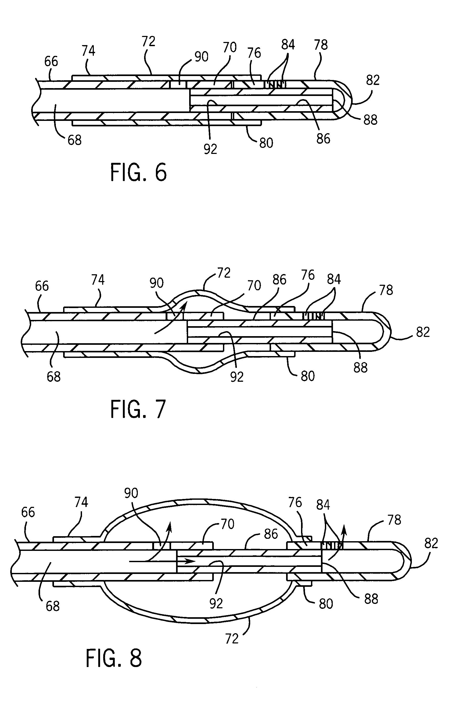
[0045]the autoinflating, autoregulating catheter assembly according to the invention is seen in FIGS. 6-8. In this embodiment, the catheter 66 has a lumen 68 extending from the luer connector (not shown) to the distal tip 70 of the catheter. The proximal end of an elastomeric balloon 72 is securely mounted to the exterior surface of the catheter 66 by conventional means to create a proximal retention collar 74. The distal end of the balloon is securely mounted to the proximal end 76 of a sliding member 78 by conventional means to create a distal retention collar 80 for the balloon 72. The sliding member 78 is substantially tubular in cross section and has a closed, distal end 82 and at least one fluid outlet aperture 84 provided a spaced distance from the proximal end 76. The sliding member 78 is telescopically and slideably received onto the distal end 88 of a guide member 86. The proximal end 92 of the guide member 86 is securely mounted to the interior of the catheter distal tip ...

third embodiment

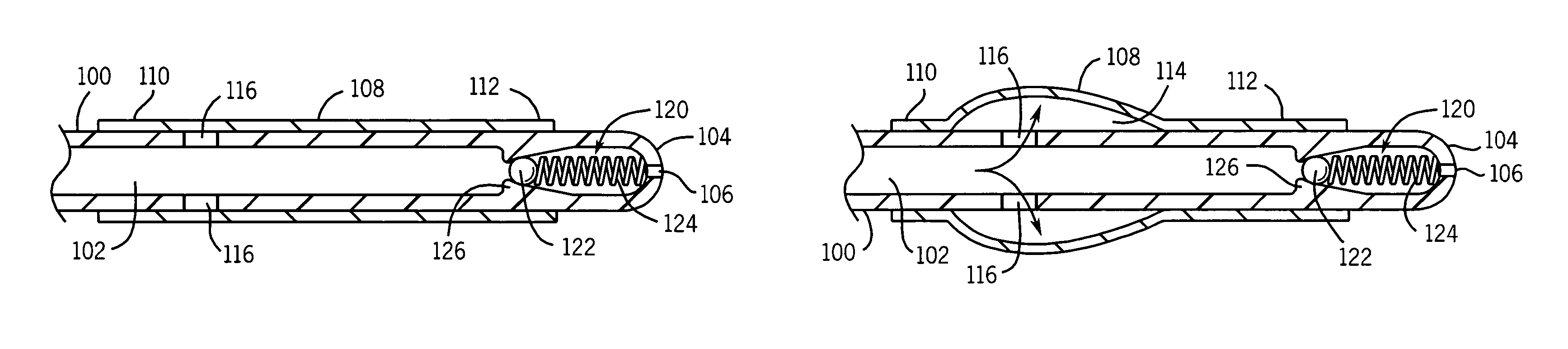
[0050]the autoregulating, autoinflation assembly according to the invention is seen in FIGS. 9-11. In this embodiment, the catheter 100 has a lumen 102 extending from a luer connector (not shown) provided on the proximal end of the catheter 100 and at least one fluid outlet aperture 106 provided on the distal end of the catheter 104. A balloon 108 formed of a tightly fitting, elastomeric material is mounted to the exterior surface of the catheter 100 by conventional means such as adhesive to create a proximal retention band 110 and distal retention band 112. The interior 114 of the balloon 108 is fluidly connected to the lumen 102 by at least one balloon aperture 116. Therefore, as pressurized fluid is supplied to the lumen 102, at least a portion of that fluid is received in the balloon 108 through the apertures 116 resulting in radial expansion of the balloon 108 from the catheter 100.

[0051]Internal valve means 120 are provided in the distal end 104 of the catheter 100 intermediat...


PUM


Abstract

An autoinflating catheter and balloon assembly having an autoregulating structure to prevent overinflation of the balloon as a result of variable fluid flow rates through the catheter lumen. A tight-fitting elastomeric balloon is provided on the distal end of the catheter body, and the assembly is constructed so that at least a portion of the fluid flow through the lumen is directed to the balloon to inflate it. As the balloon is inflated, more and more of the fluid flow through the catheter is discharged from the catheter, thereby preventing overinflation of the balloon.

Description

CROSS REFERENCE TO RELATED APPLICATIONS[0001]This is a division of application Ser. No. 10 / 235,300, filed Sep. 5, 2002, which is a division of application Ser. No. 08 / 628,763, filed Apr. 5, 1996, U.S. Pat. No. 6,458,096, which is a continuation-in-part of application Ser. No. 08 / 625,911, filed Apr. 1, 1996, U.S. Pat. No. 5,807,328, all of which are incorporated herein by reference in their entirety.BACKGROUND OF THE INVENTION[0002]1. Field of the Invention[0003]This invention relates to catheter assemblies, and more particularly, to self-inflating or autoinflating balloon catheters within the catheter and balloon assembly, including means for automatically regulating the fluid pressure inside the autoinflating balloon.[0004]2. Description of the Related Art[0005]Catheters have long been used in a wide variety of medical procedures in which the catheter is received in a bodily orifice to conduct fluid by way of the orifice. An example of one such procedure is known as retrograde card...

Claims


Application Information

Patent Timeline
Patent Type & Authority Patents(United States)
IPC IPC(8): A61M29/00A61M25/00A61F2/958A61M29/02A61M39/00
CPCA61M25/0075A61M25/10A61M25/10184A61M29/02A61M2025/1052
Inventor BRISCOE, RODERICK E.CORACE, RUSSELL A.
Owner MEDTRONIC INC
Why Eureka
Try Eureka